Canarm BI-24RM handleiding
Handleiding
Je bekijkt pagina 2 van 4
BI_BIRM_UserGuide Page 2 of 4
INSTALLATION
1. Secure the exhauster to the curb cap or sleepers (supplied by others) through the 3/4” diameter holes provided in the
base of the motor compartment and leg. For proper motor compartment ventilation, if the unit is mounted on a floor or
solid surface, provide a minimum 1” clearance to the motor cabinet bottom. Install spring isolators or duct isolators
where required.
2. Complete all subsequent duct connections.
3. Rotate the blower wheel by hand. It should not rub against the housing inlet. If rubbing occurs, loosen the setscrews
on the wheel hub and shift the wheel to obtain clearance. Re-tighten all set-screws.
4. Insert the four motor nuts and bolts up through the bottom of the sliding motor platform to match the bolting
configuration of the motor to be installed. The master hole for smaller motor frames is located at the top left hand
corner of the motor platform furthest from the blower housing. The master hole for 213T, 215T and 254T frame
motors is 2” inset from the fore mentioned master hole for smaller frame motors.
5. Mount the blower sheave on the blower shaft and tighten its set-screw securely on the key of the shaft. (See Table 1
for drive data).
6. Mount the motor sheave on the motor shaft. Leave some clearance between the pulley and the motor end bell.
Tighten the set-screws on the key of the motor shaft.
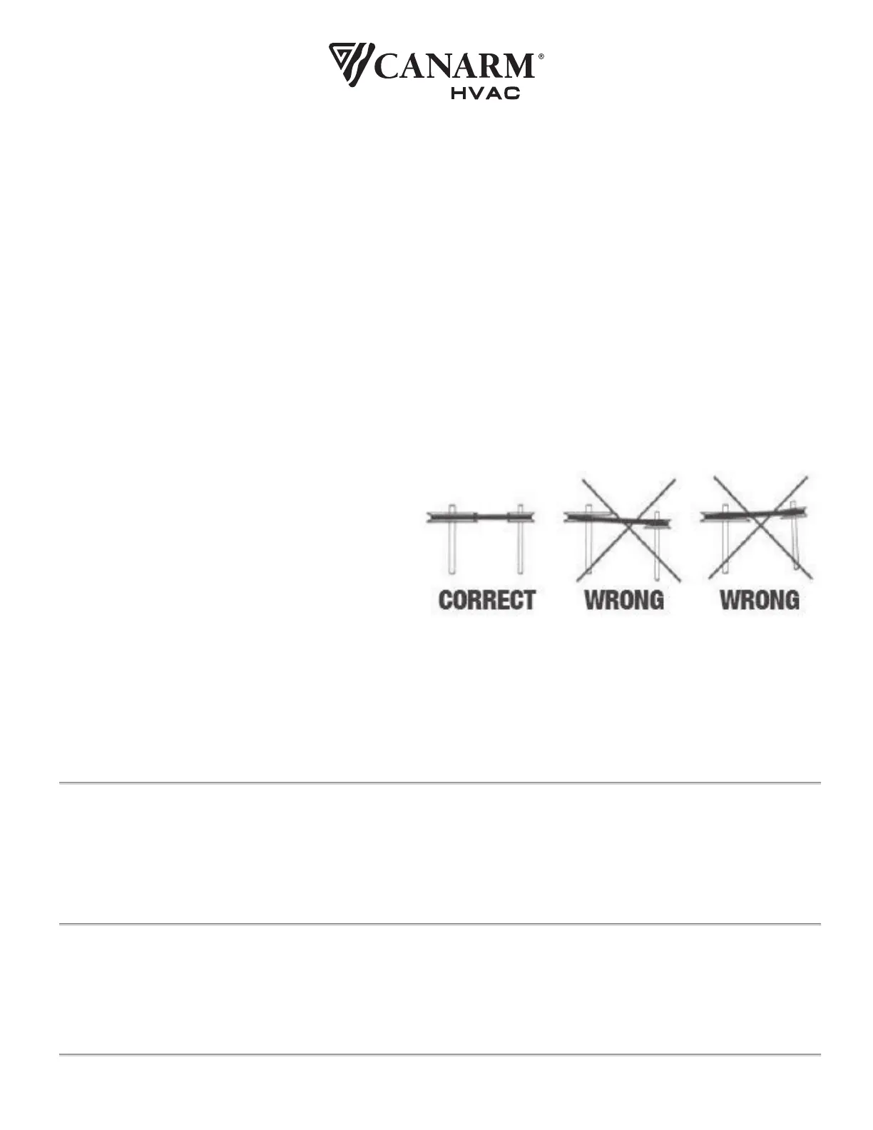
7. With the motor platform in its highest position install the V belt within the sheave grooves. Adjust the sheave on the
blower shaft to ensure proper pulley alignment (see figure 2) and secure in place. A straight edge across the face of
the driven pulley should be parallel to the belt once proper alignment has been achieved.
WARNING:
Excessive belt tension is the most frequent
cause of bearing wear and resulting noise.
Proper belt tension is critical for quiet, efficient
operation.
8. Loosen the four clamping bolts around the motor platform and slide the motor platform within the slotted rails to
adjust belt tension. Ideal belt tension is the lowest tension at which the belt will not slip during start up. As rule of
thumb suggests that 3/4” of deflection mid span under medium finger pressure (2-3 lbs.) for every foot of span is
approximately proper belt tension. Tighten the motor platform clamping bolts once proper belt tension has been
achieved.
ELECTRICAL
WARNING: Ensure power supply is disconnected and locked out prior to making electrical connections.
Before connecting the motor to the electrical supply, check the electrical characteristics and wiring instructions as
indicated on the motor nameplate or as shown below. Complete electrical connections as indicated.
WARNING: A ground wire must be connected from the motor housing to a suitable electrical ground.
OPERATION
1. After electrical connections are completed, energize the unit momentarily and ensure that the rotation of the wheel is
correct. Apply full power.
2. With the air systems in full operation and all ducts and access panels attached, measure current input to the motor
and ensure that it is less than the rated full load motor amperage.
3. Proper adjustment to the belt tension is critical for quiet efficient operation.
FIGURE 2 – PULLEY ALIGNMENT
Bekijk gratis de handleiding van Canarm BI-24RM, stel vragen en lees de antwoorden op veelvoorkomende problemen, of gebruik onze assistent om sneller informatie in de handleiding te vinden of uitleg te krijgen over specifieke functies.
Productinformatie
| Merk | Canarm |
| Model | BI-24RM |
| Categorie | Ventilator |
| Taal | Nederlands |
| Grootte | 1460 MB |


