Handleiding
Je bekijkt pagina 19 van 20
19
9. TROUBLESHOOTING
If the integrated control LED of the unit is flashing, this means the unit sensors detected a problem. See the list below to know where on
the unit the problem occurs.
LED flashes GREEN (double blink). • Thermistor error. Replace the thermistor kit.
LED flashes AMBER. • Damper error. Go to point 8.
• A few diagnosis procedures may require the unit to be in operation while proceeding. Open the unit door and
bypass its magnetic switch by putting the door white magnet on it. Be careful with moving and/or live parts.
• Risk of electric shocks. Electronic board connections must be checked by qualified personnel only.
PROBLEMS POSSIBLE CAUSES YOU SHOULD TRY THIS
1. The error code E1 is
displayed on VT7W wall
control screen.
• The wires may be in reverse position.
• The wires may be broken.
• The wires may have a bad connection.
• Ensure that the color coded wires have been connected to their appropriate
places.
• Inspect every wire and replace any that are damaged.
• Ensure the wires are correctly connected.
2. VT7W wall control screen
alternates between
normal display and E3 or
E4 appears on screen.
• The VT7W wall control needs to be
reset.
• The VT7W wall control is defective.
3. Unit does not work
(no LED is lit on the
integrated control).
• The transformer may be defective.
• The circuit board may be defective.
• The unit is unplugged.
• The unit door is opened.
• A fuse is blown.
• Wrong control connections.
• Check for 24 VAC on J8-1 and J8-2.
• Plug the unit.
• Close unit door.
• Unplug the product from the outlet. Inspect fuse on circuit board (refer to F1
on wiring diagram, page 16). If blown, discontinue using the unit and contact
technical support.
• Try the integrated control (see Section 4.1 on page 13).
4. The damper actuator
does not work or rotates
continuously.
• The damper actuator or the integrated
damper port mechanism may be
defective (integrated control LED
flashes AMBER and unit is OFF).
• The circuit board or the transformer
may be defective.(integrated control
LED flashes AMBER and unit is
OFF).
• Unplug the unit. Disconnect the main control and the optional controls(s) (if
need be). Wait 10 seconds and plug the unit back. Check if the damper opens.
If not, use a mulltimeter and check for 24 VAC on J12-1 and J12-2 (in electrical
compartment). If there is 24 VAC, replace the entire port assembly.
NOTE: It is normal to experience a small delay (7-8 seconds) before
detecting the 24 VAC signal at starting-up. This signal will stay during
17-18 seconds before disappearing.
• If there is no 24 VAC, check for 24 VAC between J8-1 and J8-2. If there
is 24 VAC replace the circuit board, and if there is no 24 VAC, change the
transformer.
5. The wall control does
not work OR its indicator
flashes.
• The wires may be in reverse position.
• The wires may be broken.
• The wire in the wall OR the wall
control may be defective.
• Ensure that the color coded wires have been connected to their appropriate
places.
• Inspect every wire and replace any that are damaged.
• Remove the wall control and test it right beside the unit using another shorter
wire. If the wall control works there, change the wire. If it does not, change the
wall control.
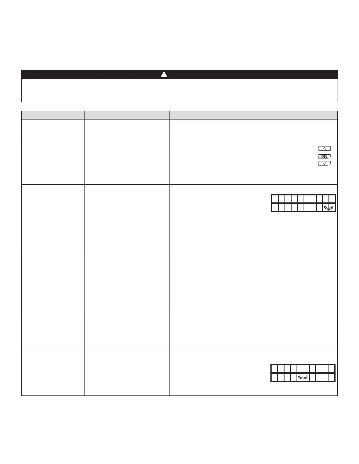
6. The VB20W push-button
does not work OR its
indicator light does not
stay on.
• The wires may be in reverse position.
• The VB20W may be defective.
• Ensure that the color coded wires have been connected to their appropriate
places.
NO C NC I OC OL Y R G B
VE0097
• Unplug the unit. Disconnect the main control
and the optional(s) control(s) (if need be).
Jump G and B terminals. Plug the unit back
and wait about 10 seconds. If the motor runs
on high speed and the damper opens, the
circuit board is not defective.
• Reset the VT7W wall control by pressing simultaneously on DOWN
arrow and OK keys for 8 seconds (as shown at right). Then, unplug
the unit for 30 seconds. Plug the unit back.
• If the problem is not solved, replace the VT7W wall control.
VQ0062
WARNING
!
• Jump the OL and OC terminals. If the
unit switches to high speed, remove the
VB20W push-button and test it right beside
the unit using another shorter wire. If it works
here, change the wire. If it doesn’t, change the
VB20W.
NO C NC I OC OL Y R G B
VE0098
Bekijk gratis de handleiding van Broan HRV150S, stel vragen en lees de antwoorden op veelvoorkomende problemen, of gebruik onze assistent om sneller informatie in de handleiding te vinden of uitleg te krijgen over specifieke functies.
Productinformatie
| Merk | Broan |
| Model | HRV150S |
| Categorie | Airco |
| Taal | Nederlands |
| Grootte | 3032 MB |


