Handleiding
Je bekijkt pagina 16 van 44
16
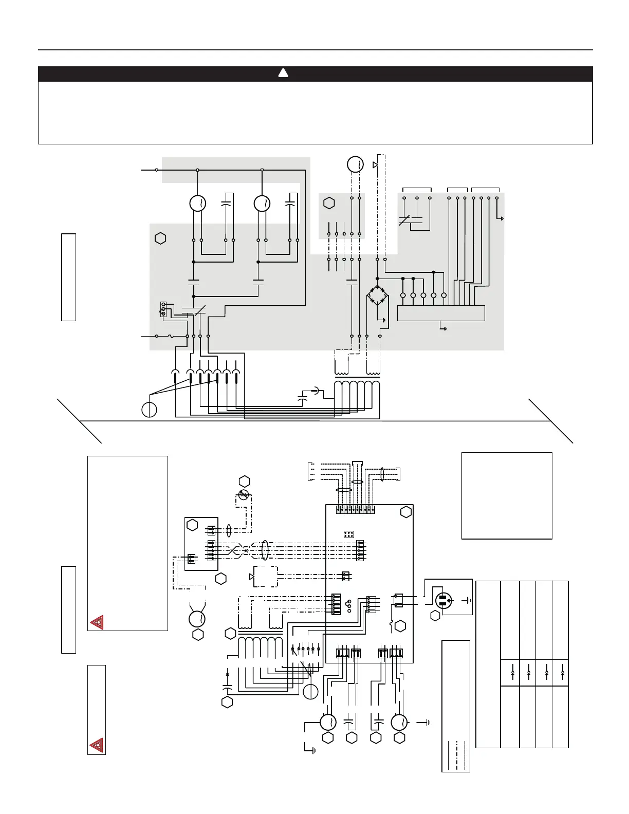
6. WIRING DIAGRAMS (CONT’D)
WARNING
• Risk of electric shocks. Before performing any maintenance or servicing, always disconnect the unit from its
power source.
• This product is equipped with an overload protection (fuse). A blown fuse indicates an overload or a short-circuit
situation. If the fuse blows, unplug the product from the outlet. Discontinue using the unit and contact technical
support.
!
Field wiring
remote control
(see notes 3 & 4)
120 V, 60 Hz
W1
J5
J7
J6
J4
ELECTRONIC
ASSEMBLY
1
2
3
1
2
1
2
1
2
3
1234
12
12345
12345
J8
J9
J11
J10
12
J12
J13
J14
10
9
8
7
6
5
4
3
2
1
BK
24 V
class 2
9.5 V
class 2
120V, 60Hz
Neutral
120 V, 60 Hz
Line
CPU
K2
K4
K5
J5-2
J10-1J10-2
Line voltage factory wiring
Class 2 low voltage factory wiring
Class 2 low voltage field wiring
See note 1
120 V
106 V
81 V
neutral
Door interlock switch
(magnetically actuated
Exhaust fan
motor
1234512
12
J3
J2
J1
t°
Damper motor
BK
Override
switch
Furnace blower interlock
J14-1 : NO
J14-2 : COM
J14-3 : nc
(optional; see notes 3, 5)
DAMPER
ELECTRONIC ASSEMBLY
Defrost
temperature sensor
WIRING DIAGRAM
LOGIC DIAGRAM
Exhaust fan motor
Supply fan motor
J5-1
J5-3
J7-2
J7-1
J4-1
J4-3
J6-2
J6-1
K1
K3
K2
24 V
class 2
9.5 V
class 2
120 V
neutral
J9-1
J9-2
J9-3
J4-2
J9-4
Exhaust fan motor
capacitor
Supply fan motor
capacitor
J8-1
J8-2
J8-4
J8-5
K4
J12-2
J12-1
A1
Damper motor
J3-2
J3-1
J2-2
J2-1
F1
J12-5
J12-4
J12-3
J2-3
J2-4
J2-5
Door interlock switch
J11-2
J11-1
K1
K3
K5
J14-3
J14-1
J14-2
Furnace
blower
interlock
(optional; see
notes 3, 5)
J14-4
J14-5
J14-6
J14-7
J14-8
J14-9
J14-10
Override
switch
(optional; see
notes 3, 4)
Field wiring
remote
control (see
notes 3, 4)
ICP
BK
YRG
W W
BK
W
BL
G
BK
BL
BN
BN
R
R
R
R
BK
BL
Exhaust fan
motor
capacitor
Supply fan
motor
capacitor
Supply fan
motor
G
G
O
O
Y
Y
BK
W
A2
A2
M3
T1
S1
R1
A1
F1
M1
C1
C2
M2
(optional; see
notes 3 & 4)
VE0439A
COLOR CODE
BK BLACK
BL BLUE
BN BROWN
G GREEN
RRED
W WHITE
Y YELLOW
nc no connection
Critical characteristic.
reed switch)
JU1
1
23
MED HI
321
HI MED
JU1
NOTES
1. Protected against fire with
UL listed/CSA Certified line fuse (3A, 3AG Type).
2. If any of the original wire, as supplied, must
be replaced, use the same equivalent wire.
3. Field wiring must comply with applicable
codes, ordinances and regulations.
4. Remote controls (class 2 circuit) available,
see instruction manual.
5. Furnace fan circuit must be class 2 circuit only.
Ref
1
Ref
1
FAN MOTORS SPEED SELECTION
SETTING Ref 1 LOW SPEED SETTING
Factory shipped Low (71V)
Optionnal Low 1 Low (81V)
Optionnal Low 2 Low (64V)
BN R
PR
GR R
71 V
64 V
57 V
R
BL
BL
R
BK
P
P
BN
BN
GR
GR
nc
nc
nc
GR GREY
OORANGE
PPURPLE
O
O
Y
Y
106 V
81 V
71 V
64 V
57 V
BK
W
BL
R
P
BN
GR
BK
W
BL
R
P
BN
GR
120 V
106 V
81 V
71 V
64 V
57 V
R
nc
BK
Low speed
capacitor
C1
BK
BL
MED
R
LO
BK
Low speed
capacitor
BK
Optionnal Low 3 Low
BK R
(Low speed capacitor)
ref: 24602_REV-A
ERV120T, ERV120S, HRV120T AND HRV120S
Bekijk gratis de handleiding van Broan ERV120T, stel vragen en lees de antwoorden op veelvoorkomende problemen, of gebruik onze assistent om sneller informatie in de handleiding te vinden of uitleg te krijgen over specifieke functies.
Productinformatie
| Merk | Broan |
| Model | ERV120T |
| Categorie | Airco |
| Taal | Nederlands |
| Grootte | 6382 MB |


