Handleiding
Je bekijkt pagina 22 van 24
22
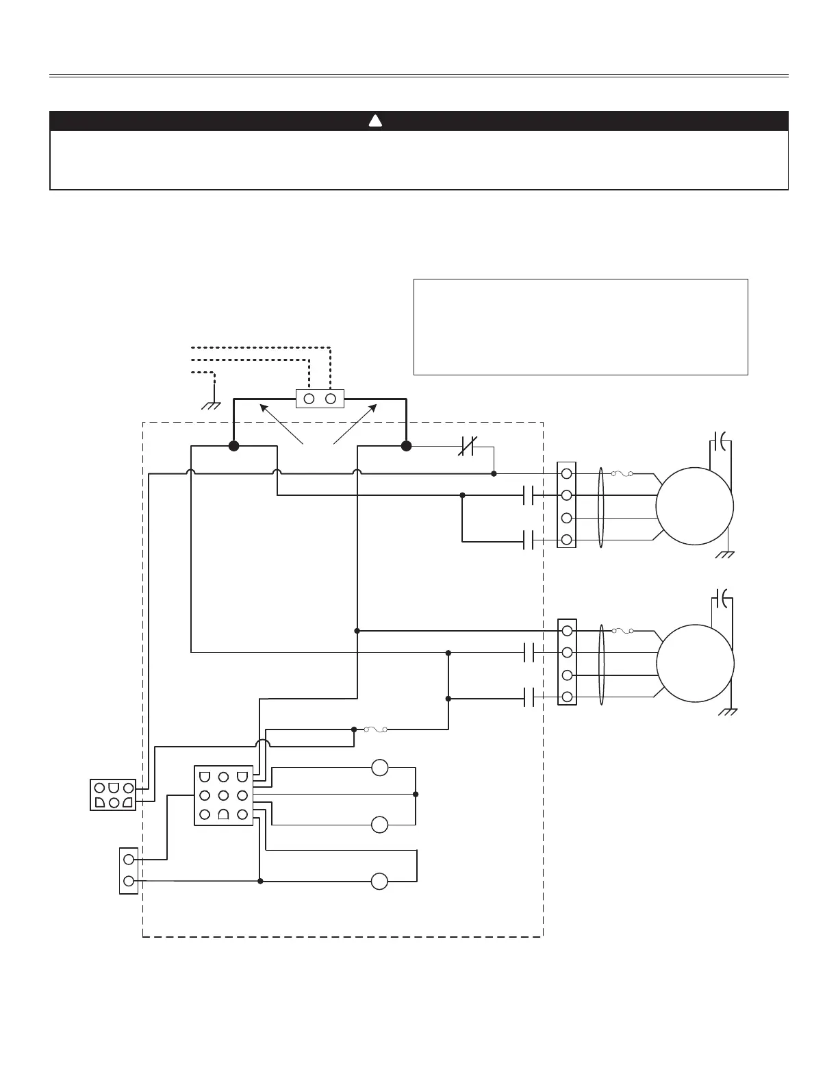
Appendix H (cont’d)
WIRING DIAGRAMS
COM
LOW
MED
HIGH
WH
R
BL
CN2
CN1
WHBK
LINE
NEUTRAL
120 VAC FIELD
WIRING
14 AWG
K1-1
K2-1
TP
M1
(Exhaust)
COM
LOW
MED
HIGH
WH
R
BL
BK/Y
CN3
K1-2
K2-2
TP
J1.1
J1.3
J1.4
J1.5
K2
J1.6
K1
BL
WH/Y
O
BK
WH
K3
J1.9
J1.8
CN5
J1
CN5.2
CN5.1
F1
BK
BK/Y
M2
(Supply)
Main Electrical Enclosure
G/Y
G/Y
G
GND
1
2
K3
1
2
3
4
1
2
3
4
WH/BL
BK/R
CN4
1
2
B6LC, B12LC - Exhaust Defrost - Normal Low Speed (cont’d)
BK
BK/R
BK/Y
BL
BN
G
G/Y
O
R
WH
WH/BL
WH/R
WH/Y
Y
BLACK
BLACK/RED
BLACK/YELLOW
BLUE
BROWN
GREEN
GREEN/YELLOW
ORANGE
RED
WHITE
WHITE/BLUE
WHITE/RED
WHITE/YELLOW
YELLOW
WIRING COLOR CODE
BN
BN
BN
BN
5
6
4
2
3
1
LOGIC DIAGRAM
VE0469A
Ref: 1107006_REV-A
123
456
9 78
J1.2
WH/R
BK
BK
BK
BK
BK
BK
BK
BK
WH WH
WH
WH
WH
BK/R
BK/R
WARNING
• Risk of electric shocks. Before performing any maintenance or servicing, always disconnect the unit from its power source.
• This product is equipped with an overload protection (fuse). A blown fuse indicates an overload or a short-circuit situation.
If the fuse blows, disconnect the unit from its power source. Discontinue using the unit and contact technical support.
!
Bekijk gratis de handleiding van Broan B6LCEPSN, stel vragen en lees de antwoorden op veelvoorkomende problemen, of gebruik onze assistent om sneller informatie in de handleiding te vinden of uitleg te krijgen over specifieke functies.
Productinformatie
| Merk | Broan |
| Model | B6LCEPSN |
| Categorie | Airco |
| Taal | Nederlands |
| Grootte | 3451 MB |


