Handleiding
Je bekijkt pagina 18 van 24
18
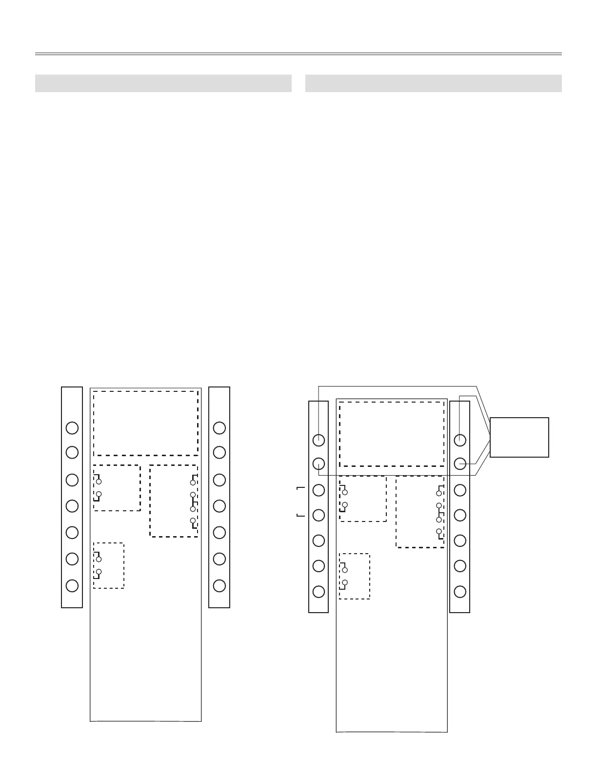
Appendix E
TERMINAL CONTROL DIAGRAMS
A low voltage remote control wiring interface is provided on
the unit. The connections for the low voltage remote wiring are
located on two terminals adjacent to the exhaust fan outlet (or
adjacent to the supply fan outlet on the B1600705 unit). All eld
installed wiring must be low voltage class II.
REMOTE WALL CONTROL
Optional wall control requires a 4 wire LVT-24 gauge (or
equivalent). This remote wall control runs on 12 VDC.
LOW VOLTAGE CONTROLS
All other terminals are dry contacts.
Low Voltage terminal control consists of the following:
WALL CONTROL
4 wire LVT 24 gauge minimum
OCCUPIED (NIGHT SET BACK) TIMER/SENSOR
24 VAC, needs dry contact
LOW - COM - HIGH
Remote fan switching requires a single pole, double throw switch
(SPDT)
FAN INTERLOCK RELAY OUTPUT (FF)
Dry contact closes on ventilation or defrost. Used to control
external fan.
One type of remote wall control is available: the Slide Switch Wall
Control with fan switch and dehumidistat control.
The remote wall controls work with the microprocessor electronic
control within the unit to control ventilation sequences. This wall
control requires a 4-wire connection to the unit as shown below.
Without the wall control, fans can be operated with a remote fan
switch as shown in Appendix E-4.
NOTE:
When using a wall control, never use the the LOW, COMMON and
HIGH terminals.
E-1: TERMINAL LABEL E-2: WALL CONTROL CONNECTION
VE0466A
Wall
Control
JUMPER
WALL CONTROL
COMMANDE MURALE
NOTE:
Use of 24 VAC circuit
requires isolating contacts
(ex. thermostat) to prevent
interconnection of Class 2
outputs.
Black/Noir
ON-OFF/
MARCHE-
ARRÊT
LOW
BASSE
COMMON
COMMUN
HIGH
HAUTE
Green/Vert
Red/Rouge Yellow/Jaune
F
F
CLASS 2 LOW
VOLTAGE /
CLASSE 2 BASSE
TENSION
L'utilisation d'un circuit 24
VCA nécessite des contacts
isolés (ex. thermostat) pour
éviter l'interconnexion des
sorties de Classe 2.
Bekijk gratis de handleiding van Broan B6LCEPSN, stel vragen en lees de antwoorden op veelvoorkomende problemen, of gebruik onze assistent om sneller informatie in de handleiding te vinden of uitleg te krijgen over specifieke functies.
Productinformatie
| Merk | Broan |
| Model | B6LCEPSN |
| Categorie | Airco |
| Taal | Nederlands |
| Grootte | 3451 MB |


