Handleiding
Je bekijkt pagina 15 van 52
15
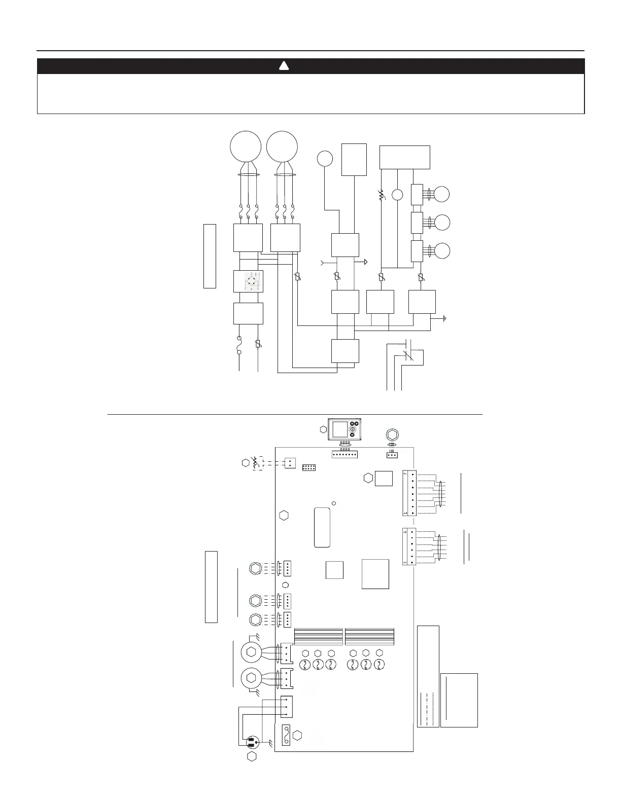
4. WIRING DIAGRAM
BLK
BLK
GRN
LOGIC DIAGRAM
WIRING COLOR CODE
BLKBLACK
BLUBLUE
GRNGREEN
REDRED
WHTWHITE
Line voltage factory wiring
Low voltage factory wiring
Low voltage field wiring
(Exhaust)
BLU
RED
120VAC
60Hz
W1
GRN
1
Power
LED
J1
M3
Damper Stepper Motors
Y
M1
WHT
BLK
A1
MAIN ELECTRONIC
ASSEMBLY
M1
Power
Supply
(15VDC)
Line
Neutral
K1
G
Gf
AC
Line
Filter
J1-2
F1
High Voltage
(120VAC)
J1-1
To J2
MCU
K1
M3
Stepper
Driv er
To J5
WIRING DIAGRAM
BDM
1
J2 J3 J5 J6
J7
1
111
1
J7a
J15a
1
A2
LCD
ASSEMBLY
GRN
Venlaon Fan Motors
BLU
RED
M2
M4 M5
(Supply)
(Supply)
(Recirc) (Exhaust)
MCU
Serial Number
Isolaon
Transformer
Motor Fuses
F3
F6
F5
F7
V W GfC G R
* Oponal AHU Wiring
(Isolated 24VAC)
OVR
LED
12V
D-
D+
GND
Main and Auxilliary
Controls Wiring
Thermi stor
R1
RT1
(NTC)
Bridge
IPM
Motor 1
IPM
Motor 2
F3
F2
M2
To J3
F
F4
AHU
Relay
K1
PTC3
Isolated
Supply
(12VDC)
Isolated
Supply
(3.3VDC)
J9
J13
Logic
Supply
(3.3VDC)
PTC2
To J9
Logic
Supply
(12VDC)
M4
Stepper
Driv er
To J6
M5
Stepper
Driv er
To J7
PTC6
PTC4
To J13
R
TH1
To J7a
(R1)
LCD
Assembly
Isolated GND
Digital GND
To J15a
(A2)
J14
F2
F4
J16a
M6
Cooling
Fan
F7
F
M6
To J16a
F1
5A/125VAC
* 210-230 CFM
Models only
* 210-230 CFM
Models only
VE0481A
6
5
WARNING
• Risk of electric shocks. Before performing any maintenance or servicing, always disconnect the unit from its power source.
• This product is equipped with an overload protection (fuse). A blown fuse indicates an overload or a short-circuit situation. If the fuse blows, unplug the
product from the outlet. Discontinue using the unit and contact technical support.
!
Bekijk gratis de handleiding van Broan B180H75RT, stel vragen en lees de antwoorden op veelvoorkomende problemen, of gebruik onze assistent om sneller informatie in de handleiding te vinden of uitleg te krijgen over specifieke functies.
Productinformatie
| Merk | Broan |
| Model | B180H75RT |
| Categorie | Airco |
| Taal | Nederlands |
| Grootte | 7564 MB |


