Bolin Technology R9-230NX handleiding
Handleiding
Je bekijkt pagina 11 van 49
Subnet Mask: 255.255.255.0
Subnet Mask: 255.255.255.0
Gateway: 192.168.0.1
Gateway: 192.168.0.1
To change these settings, refer to the
To change these settings, refer to the
Web Interface Conguration
Web Interface Conguration
section of this guide.
section of this guide.
Video Output
The R9 has multiple video outputs, which can be used simultaneously, and the resolutions can be congured independently. The outputs vary based on the camera
model and are as follows:
HDMI Out (HDMI 1.4 in R9-230H)
The user should follow these steps to connect the camera:
1. Connect one end of an HDMI cable that supports the required resolution to the HDMI Output of the camera. Connect the other end of the HDMI cable to the
desired destination (Switcher, Converter, Display, etc.).
2. Power on the camera and wait for it to initialize. Once initialized, video will appear on the screen. For the rst ve seconds, the camera’s initial settings will be
displayed.
3. The user can utilize the OSD (On-Screen Display) Menu or Web Interface to set the desired output resolution and frame rate. For more information on how to
congure these settings, please refer to the Web Interface Conguration and System Menu section of this guide.
NOTE:
NOTE:
It is recommended for the user to utilize a certied “Premium High Speed HDMI” cable to guarantee the attainment of the maximum signal
It is recommended for the user to utilize a certied “Premium High Speed HDMI” cable to guarantee the attainment of the maximum signal
quality from their camera.
quality from their camera.
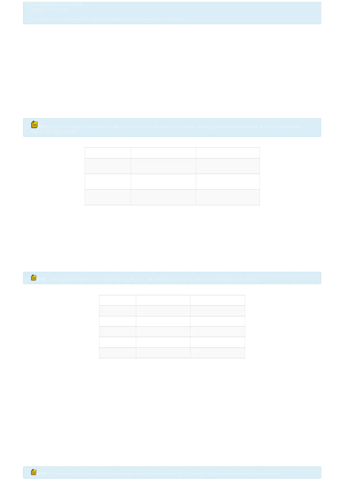
HDMI Standard Classications
HDMI Standard Bandwidth Max Resolution Supported
HDMI 1.4 10.2 Gigabit/Second
1080p,120 Hz
4K, 30 Hz
HDMI 2.0 18.0 Gigabit/Second
4K, 60 Hz
HDMI 2.1 48.0 Gigabit/Second
8K, 120 Hz
Dual SDI Out(3G-SDI in R9-230H)
1. Connect one end of an appropriately rated SDI cable to one of the two SDI outputs on the camera. Ensure to secure the BNC connector in place to prevent the
cable from becoming loose during use. Connect the other end of the SDI cable to the desired destination (Switcher, Video Router, Converter, Display, etc.).
2. Power on the camera and wait for it to initialize. Once initialized, video will appear on the screen. For the rst ve seconds, the camera’s initial settings will be
displayed.
3. The user can utilize the OSD (On-Screen Display) Menu or Web Interface to set the desired output resolution and frame rate. For more information on how to
congure these settings, please refer to the Web Interface Conguration and System Menu section of this guide.
NOTE:
NOTE:
The SDI Output labeled as "Program Out" or "P/G Out" will only display the video and not any OSD Menu's or overlays.
The SDI Output labeled as "Program Out" or "P/G Out" will only display the video and not any OSD Menu's or overlays.
SDI Standard Classications
SDI Standard Bandwidth Resolution Supported
SD-SDI 270 Megabits/Second 480i
HD-SDI 1.485 Gigabit/Second 720p / 1080i
3G-SDI 2.970 Gigabit/Second 1080P, 60FPS
6G-SDI 6 Gigabit/Second 4K, 30FPS
12-SDI 12 Gigabit/Second 4K, 60FPS
Optical Fiber
Obtain (2x) single-mode 1310 nm SFP+ 12G optical modules (transceivers) with LC duplex ber connectors to plug into each end of the signal chain. Additionally,
acquire a single-mode duplex ber cable with LC connectors that is the appropriate length for the user’s requirements.
1. Insert one SFP+ module into the camera. Once the module is fully inserted, connect the ber cable to the LC connectors of the module. Repeat these steps at
the receiving end of the signal chain (Fiber Converter, Monitor, Recorder, etc.).
2. Power on the camera and wait for it to initialize. Once initialized, video will appear on the screen. For the rst ve seconds, the camera’s initial settings will be
displayed.
3. You can use the OSD (On-Screen Display) Menu or Web Interface to set the desired output resolution and frame rate. Please see the Web Interface Conguration
and System Menu section of this guide for more information on how to congure these settings.
4. The user can utilize the OSD (On-Screen Display) Menu or Web Interface to set the desired output resolution and frame rate. For more information on how to
congure these settings, please refer to the Web Interface Conguration and System Menu section of this guide.
After conducting thorough testing, we recommend the brands FS and LR-TECH for your needs. In particular, the ‘LR-8910D-SDI-LR’ model (Serial Number:
BS190909052) was found to perform exceptionally well.
NOTE
NOTE
:
:
The resolution of the Optical Fiber is the same as the resolution set for the SDI outputs. These video outputs are not independent.
The resolution of the Optical Fiber is the same as the resolution set for the SDI outputs. These video outputs are not independent.
Bekijk gratis de handleiding van Bolin Technology R9-230NX, stel vragen en lees de antwoorden op veelvoorkomende problemen, of gebruik onze assistent om sneller informatie in de handleiding te vinden of uitleg te krijgen over specifieke functies.
Productinformatie
| Merk | Bolin Technology |
| Model | R9-230NX |
| Categorie | Bewakingscamera |
| Taal | Nederlands |
| Grootte | 10466 MB |


