Best HBN1366SS handleiding
Handleiding
Je bekijkt pagina 2 van 8
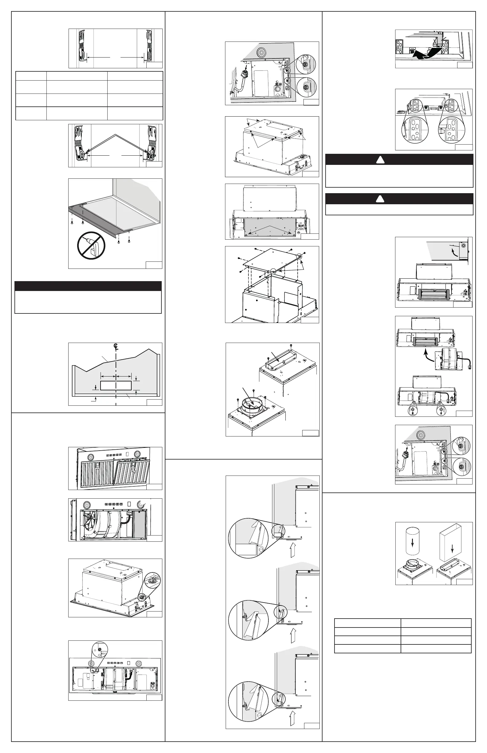
4. PREPARE THE CABINET (cont’d)
This powerpack insert is factory shipped to exhaust vertically; however, it is
possible to make it exhaust horizontally (3¼” x 10” ducting only).
8. Cut the hole for the
horizontal exhaust
through the back wall
of the cabinet using
the dimensions shown.
(FIG. 13).
Horizontal exHaust installation only
5¼"5¼"
3½"
3/4"
HH0318A
FIG. 13
CABINET BOTTOM
CABINET
BACK WALL
8. From inside the unit,
detach the back plate
(grey part in FIG. 20)
by removing its both
retaining nuts using 3/8”
diameter socket. Set
aside the nuts and plate.
6. INSTALL THE UNIT (cont’d)
HD1352
FIG. 21
HOLES
9. Install the back plate on
top of the unit, where
the blower support plate
was. Orient the holes
nearby the corners
towards the back of the
unit. Assemble to the top
of the unit using 6 screws
previously removed in
step 7 (FIG. 21).
5. PREPARE THE UNIT
all installations
1. If present, remove all protective polyfilm from the unit and/or parts.
2. Remove the hybrid
baffle filters by pushing
down on latch tab
and tilting the filters
downward (FIG. 14).
Set aside the filters.
3. Disassemble the
electrical compartment
cover (grey part in
FIG. 15) from inside
the unit by removing
its retaining screw.
Remove the parts bag
behind the cover. Set
aside the parts bag and
the cover along with its screw.
HD1411
FIG. 14
HD1412
SCREW
FIG. 15
4. Punch out one of the
two knock-out holes.
Install an appropriate
7/8” diameter strain
relief (not included,
grey part in FIG. 16).
NOTE: The HCK44
cord connection kit
(optional) can be used
instead of the house
power cable. Refer to
the instruction packed
with the HCK44 cord connection kit.
HD1358
FIG. 16
Horizontal exHaust installation only
5. Remove and discard
the screw circled in
FIG. 17.
NOTE: This screw
might be present or
not.
HD1435
FIG. 17
HD1350
FIG. 20
NUTS
Vertical exHaust installation only
10. For rectangular
ducting, use 2 included
no. 8-18 x 1/4” metal
screws to attach the
included 3¼” x 10”
adapter damper on top
of the unit, over the
blower exhaust opening
(FIG. 22).
NOTE: The damper hinge
must be towards the
front of the unit.
For round ducting,
use 4 included
no. 8-18 x 1/4”
metal screws to attach
the included 6-in. round
(or 8-in. round) adapter
damper on top of the
unit, over the blower exhaust opening (FIG. 22, 6-in. round shown).
NOTE: The damper hinge must be parallel to the sides of the unit.
FIG. 22
HJ0255
HINGE
HINGE
6. INSTALL THE UNIT
1. Run house power cable
between service panel
and unit location. Stub out
a 2-foot length of power
cable inside the cabinet.
Insert the power cable
in the unit through the
7/8” diameter strain relief
previously installed.
NOTE: Not necessary if
the optional HCK44 cord
connection kit is used.
2. Insert the unit in the
cabinet, until you feel a
‘click’ from both sides
of the unit, confirming
that the Ease of Install
hooks rest on the top of
the cabinet bottom sides
, or cabinet brackets
or (FIG. 23). Move
the unit from left to right,
from rear to front and up
to ensure the Ease of
Install hooks are retaining
the unit inside the cabinet.
NOTE: The unit will be
protruding below the
cabinetry until tightened.
HD1374
FIG. 23
4. From inside the unit, slide the
3¼” x 10” adapter/damper in
the horizontal duct, then attach
it to the unit using aluminum
duct tape all around the joint
(FIG. 26). Ensure the damper
opens as shown in damper
side view.
Horizontal exHaust installation only
HJ0258
FIG. 26
DAMPER
SIDE
VIEW
DUCT
5. Insert the blower with its support
plate inside the unit, where
the back plate was initially
(A). Attach to the unit using
2 nuts previously removed in
step 8 in PREPARE THE UNIT
section (B) (FIG. 27).
FIG. 27
HO0415
A
B
6. Reinstall and secure the
faceplate to the unit using its
4 retaining screws (two per side,
circled in FIG. 28). Plug the
blower cable to its connector on
faceplate (FIG. 28).
HD1445
FIG. 28
HJ0256
FIG. 29
7. CONNECT DUCTWORK
Vertical exHaust installation only
Ducted Installation
Use 6-in. round, 8-in. round
or 3¼” x 10” metal duct to
connect the adapter damper
on the top of the unit to the
ductwork above (FIG. 29, 8-in.
round not shown). Seal the
joint using aluminum duct tape.
Non-Ducted Installation
A non-duct kit is required for this type of installation (purchase
separately). To install, follow the instructions packed with the kit.
Refer to table below to find the appropriate non-duct kit according to
the unit.
Unit model non-dUct kit model
HBN1246SS HARKBN24
HBN1306SS HARKBN30
HBN1366SS HARKBN36
3. Lift the unit until contact is made
between the unit flange and
cabinet. Secure the unit to the
cabinet using 4 no. 8 x 5/8” wood
screws included in parts bag
(2 screws per side). Use upper
or lower holes (1, 2, 3, 4, 5 or
6) (FIG. 25).
WARNING
The Ease of Install hooks TEMPORARILY hold the unit in
place. The unit MUST BE secured to the cabinet using the
included 4 screws.
!
WARNING
Never use this unit as a shelf.
!
HD1384
1
2
3
4
5
6
1
2
3
4
5
6
FIG. 25
5. PREPARE THE UNIT (cont’d)
7.
Remove the
6 screws (2
per side and 2 in front)
retaining the blower
support plate to the top
of the unit (FIG. 19).
Carefully lift out and set
aside the blower with its
support plate. The blower
will be reinstalled later in
the unit.
6. Measure the distance
between both bottom
bracket edges (F)
(FIG. 10). The table
below shows the
approriate distance
needed.
If the measured distance
needs to be shortened,
screw two no. 8-32 x 1/4”
machine screws, in each
bottom embossed cabinet
brackets hole; this will
slightly bend the bottom
part of the brackets
(FIG. 11). Screw both
brackets until the appropriate distance is obtained.
F
HD1376
FIG. 10
F
HD1377
Screws in bottom
embossed holes
FIG. 11
Unit narrow edge wide edge
HBN1246SS
F
From 21-7/8” to < 22-1/16”
F
From 22-1/16” to 22-5/16
”
HBN1306SS
F
From 27-7/8” to < 28-1/16”
F
From 28-1/16” to 28-5/16”
HBN1366SS
F
From 33-7/8” to < 34-1/16”
F
From 34-1/16” to 34-5/16”
7. Optional
There are 7 different
sizes of optional fillers
(sold separately)
designed to fit up to
15-in. depth cabinets
(for HBN1246SS unit,
order: HADTBN24,
for HBN1306SS:
order HADTBN30,
for HBN1366SS:
order HADTBN36).
Choose the filler that
fits better to cover
the back bottom
edge of the cabinet.
Use 4 no. 6 x 1/2”
truss head wood screws (included in the optional kit) to mount it (FIG. 12).
HD1373
FIG. 12
CAUTION
Never use an electric screwdriver or drill to screw the
filler to the bottom edge of cabinet; use a standard
screwdriver.
NOTE: If, for any reason, the unit
has to be removed from
the cabinet, it is possible
to disengage the Ease of
Install hooks. To do so,
while holding and pushing
on one side of the unit,
lift simultaneously Ease of
Install hooks levers (1 and 2, grey parts in FIG. 24) in the other side
of the unit until the hooks are retracted.
HD1375
FIG. 24
1
2
Horizontal exHaust installation only (cont’d)
6. Unplug the blower cable
from its connector on
faceplate. Disassemble
the faceplate from the
unit by removing its
4 retaining screws
(two per side, circled in
FIG. 18). Set aside the
faceplate along with its
screws.
HD1444
FIG. 18
HD1428
FIG. 19
SCREWS
SCREWS
SCREWS
Bekijk gratis de handleiding van Best HBN1366SS, stel vragen en lees de antwoorden op veelvoorkomende problemen, of gebruik onze assistent om sneller informatie in de handleiding te vinden of uitleg te krijgen over specifieke functies.
Productinformatie
| Merk | Best |
| Model | HBN1366SS |
| Categorie | Niet gecategoriseerd |
| Taal | Nederlands |
| Grootte | 3452 MB |


