Berner Architectural Contour 8 handleiding
Handleiding
Je bekijkt pagina 6 van 16
-6-
VI. FIELD CONNECTIONS
A. A separate line voltage supply with a suitable branch
circuit protection device should be run directly from the
main electrical panel to the unit. A disconnect switch for
each branch circuit is a required part of this installation.
See the voltage label on the unit for circuiting and total
electrical load. The wiring diagram is located in the
wiring compartment, located on the top of the unit.
See Figure 7.
B. All eld wiring must be copper with a minimum
insulation of 60°C within approved conduit. If any of the
wire supplied in the unit must be replaced, it must be
replaced with copper wire with a minimum insulation of
90°C.
C. Electric and hot water heated air curtains are factory
equipped with an unit mounted solid state temperature
sensor located internally to measure the incoming
(return) air stream.
D. Remove the wiring compartment cover.
E. Connect all supply and control circuit wires according to
the wiring diagram provided.
NOTE: For Electric and Hot Water heated air curtains
provided with an optional remote thermostat, mount
and wire the thermostat according to thermostat
instructions and wiring diagram.
For BACnet-IP Integration –
see XI - Appendix C, “BACnet-IP integration.”
For Serial Network Connection - proceed to
XI - Appendix A, “Serial/Network Connection.”
NOTE: The air curtain must have been ordered from the
factory with this option.
For Wall Mounted Touchscreen – proceed to
XI - Appendix B, “Wall Mounted Touchscreen.”
if optional remote Touchscreen control of the
Intelliswitch™ has been ordered from the factory.
For Electric and Hot Water air curtains - proceed to
Section VI - Field Connections, otherwise proceed to
Section VII - Operating Instructions
A. ELECTRICALLY HEATED MODELS
The heater circuit may be controlled by an optional
remote thermostat or through the built-in Intelliswitch™
thermostat located on top of the air curtain. Overheating
protection is provided by auto reset thermal cutouts built
into the heater coil assembly (see the wiring diagram
located in the wiring compartment). See Figure 7.
B. HOT WATER HEATED MODELS
An optional water coil solenoid valve (by others or
Berner) may be controlled through the Intelliswitch™ or
independently. The Intelliswitch™ is capable of providing
the same voltage used for the motor to power a solenoid
load up to 5 amps. This call for heat may be controlled
by an optional remote thermostat or through the built-
in Intelliswitch™ thermostat located on top of the air
curtain. Piping should be done in accordance with local
codes, regulations and standard practices. Connect
the building system to the (3/4"-AC08 or 1"- AC10) MPT
supply and return header connections. See Figure 8.
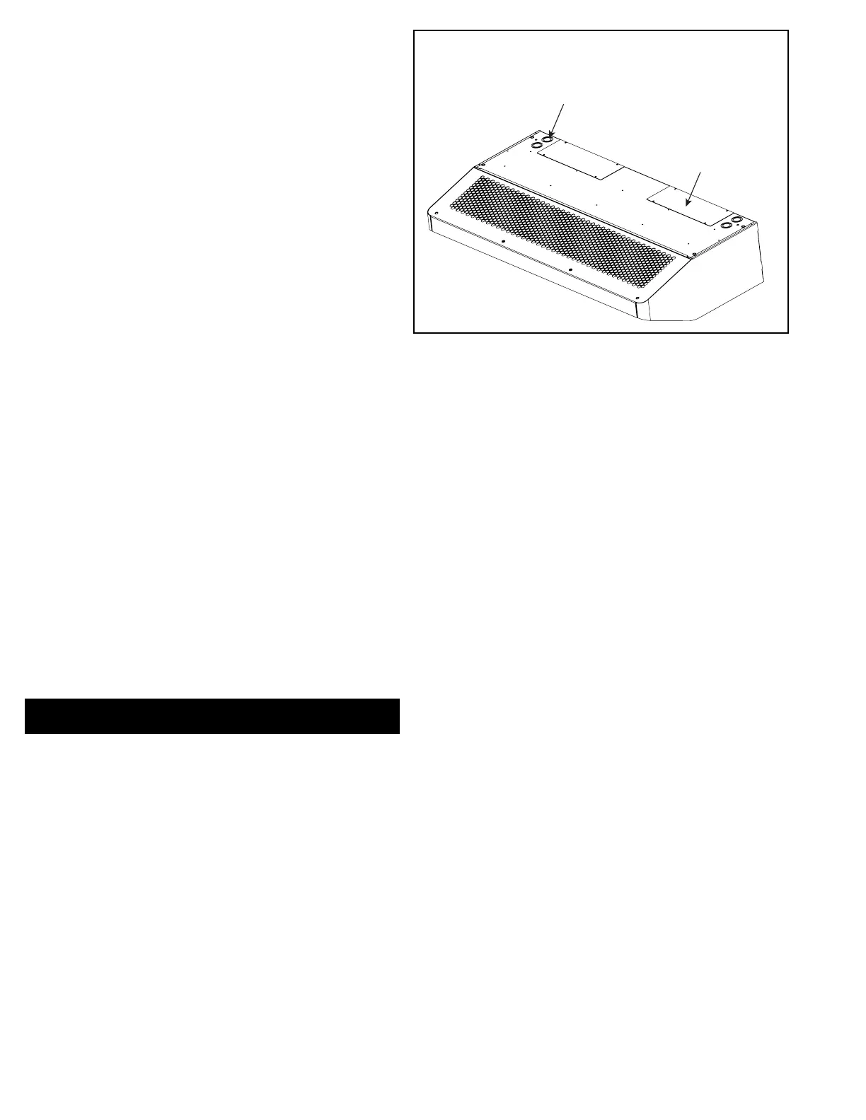
Figure 7 - Electrical Connections
WIRING
COMPARTMENT
COVER
KNOCKOUTS
FOR POWER &
CONTROL
WIRING
Bekijk gratis de handleiding van Berner Architectural Contour 8, stel vragen en lees de antwoorden op veelvoorkomende problemen, of gebruik onze assistent om sneller informatie in de handleiding te vinden of uitleg te krijgen over specifieke functies.
Productinformatie
| Merk | Berner |
| Model | Architectural Contour 8 |
| Categorie | Niet gecategoriseerd |
| Taal | Nederlands |
| Grootte | 3411 MB |


