Handleiding
Je bekijkt pagina 31 van 108
108108
Split type air conditioner / User Manual 31 / 108 EN
30 / 112 EN
Split Type Air Conditioner / User Manual
4 Installation
Outdoor Unit Dimensions (mm) Mounting Dimensions
W x H x D Distance A (mm) Distance B (mm)
681x434x285 (26.8”x 17.1”x 11.2”) 460 (18.1”) 292 (11.5”)
700x550x270 (27.5”x 21.6”x 10.6”) 450 (17.7”) 260 (10.2”)
700x550x275 (27.5”x 21.6”x 10.8”) 450 (17.7”) 260 (10.2”)
720x495x270 (28.3”x 19.5”x 10.6”) 452 (17.8”) 255 (10.0”)
728x555x300 (28.7”x 21.8”x 11.8”) 452 (17.8”) 302(11.9”)
765x555x303 (30.1”x 21.8”x 11.9”) 452 (17.8”) 286(11.3”)
770x555x300 (30.3”x 21.8”x 11.8”) 487 (19.2”) 298 (11.7”)
805x554x330 (31.7”x 21.8”x 12.9”) 511 (20.1”) 317 (12.5”)
800x554x333 (31.5”x 21.8”x 13.1”) 514 (20.2”) 340 (13.4”)
845x702x363 (33.3”x 27.6”x 14.3”) 540 (21.3”) 350 (13.8”)
890x673x342 (35.0”x 26.5”x 13.5”) 663 (26.1”) 354 (13.9”)
946x810x420 (37.2”x 31.9”x 16.5”) 673 (26.5”) 403 (15.9”)
946x810x410 (37.2”x 31.9”x 16.1”) 673 (26.5”) 403 (15.9”)
If you will install the unit on the ground or on a
concrete mounting platform, do the following:
1. Mark the positions for four expansion bolts
based on dimensions chart.
2. Pre-drill holes for expansion bolts.
3. Place a nut on the end of each expansion bolt.
4. Hammer expansion bolts into the pre-drilled
holes.
5. Remove the nuts from expansion bolts, and
place outdoor unit on bolts.
6. Put washer on each expansion bolt, then
replace the nuts.
7. Using a wrench, tighten each nut until snug.
A
WARNING! When drilling into
concrete, eye protection is
recommended at all times.
If you will install the unit on a wall-mounted
bracket, do the following:
A
CAUTION! Make sure that the
wall is made of solid brick,
concrete, or of similarly strong
material. The wall must be able
to support at least four times the
weight of the unit.
1. Mark the position of bracket holes based on
dimensions chart.
2. Pre-drill the holes for the expansion bolts.
3. Place a washer and nut on the end of each
expansion bolt.
4. Thread expansion bolts through holes in
mounting brackets, put mounting brackets in
position, and hammer expansion bolts into the
wall.
5. Check that the mounting brackets are level.
31 / 112 EN
Split Type Air Conditioner / User Manual
6. Carefully lift unit and place its mounting feet on
brackets.
7. Bolt the unit firmly to the brackets.
8. If allowed, install the unit with rubber gaskets
to reduce vibrations and noise.
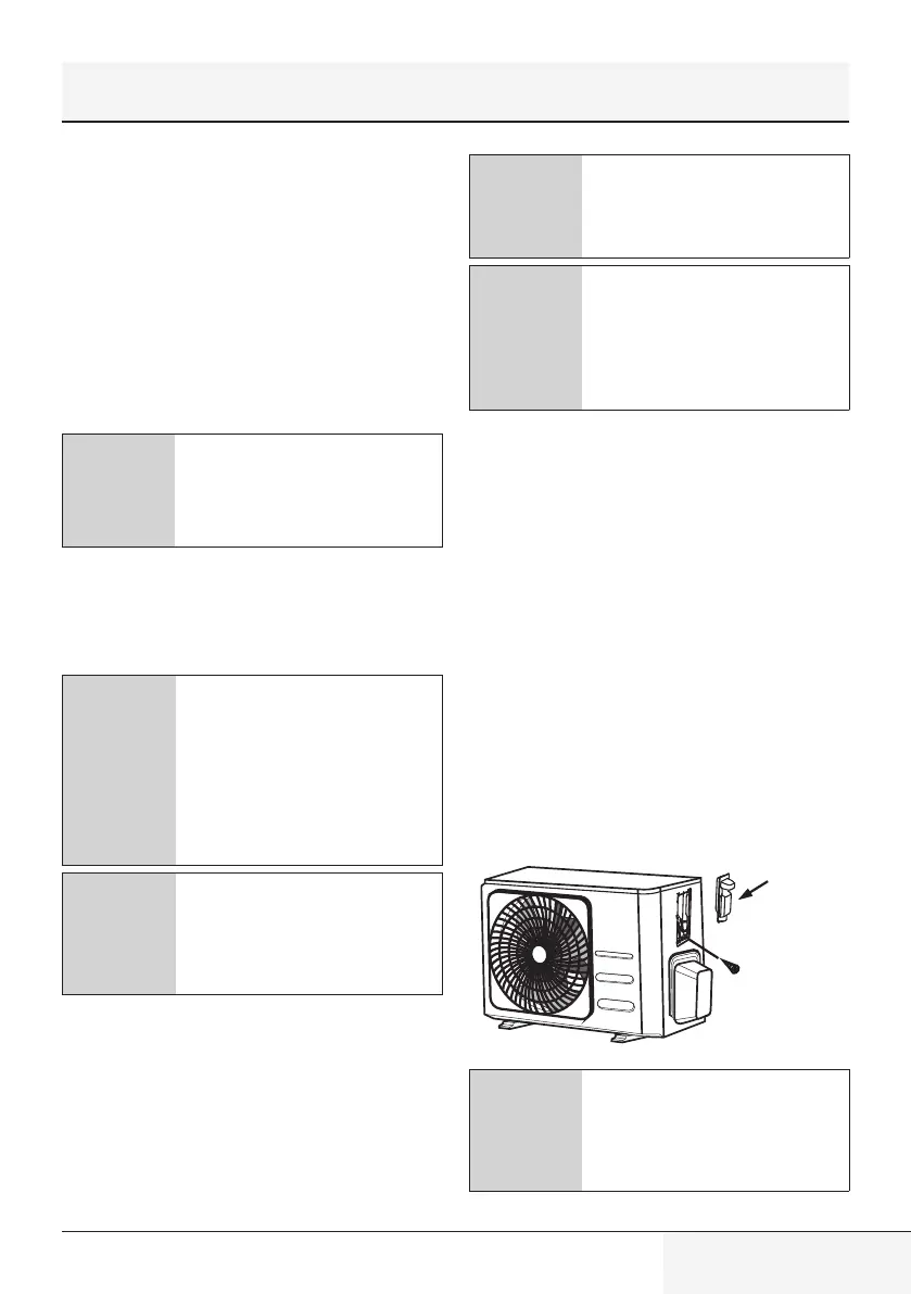
Step 4: Connect signal and power cables
The outside unit’s terminal block is protected by
an electrical wiring cover on the side of the unit.
A comprehensive wiring diagram is printed on
the inside of the wiring cover.
A
WARNING! Before performing
any electrical or wiring work,
turn off the main power to the
system.
1. Prepare the cable for connection: Please
choose the right cable refer to “ Cable types”
in page 24.
C
The size of the power supply
cable, signal cable, fuse, and
switch needed is determined
by the maximum current of the
unit. The maximum current is
indicated on the nameplate
located on the side panel of the
unit.
C
In North America, please choose
the right cable size according to
the minimum circuit ampacity
indicated on the nameplate of
the unit.
• Using wire strippers, strip the rubber jacket
from both ends of cable to reveal about 40mm
(1.57in) of the wires inside.
• Strip the insulation from the ends of the wires.
• Using a wire crimper, crimp u-lugs on the ends
of the wires.
C
While crimping wires, make
sure you clearly distinguish the
Live (“L”) Wire from other wires.
A
WARNING! All wiring work
must be performed strictly in
accordance with the wiring
diagram located inside of wire
cover of the outdoor unit.
2. Unscrew the electrical wiring cover and remove
it.
3. Unscrew the cable clamp below the terminal
block and place it to the side.
4. Connect the wire according to the wiring
diagram, and firmly screw the u-lug of each
wire to its corresponding terminal.
5. After checking to make sure every connection
is secure, loop the wires around to prevent rain
water from flowing into the terminal.
6. Using the cable clamp, fasten the cable to the
unit. Screw the cable clamp down tightly.
7. Insulate unused wires with PVC electrical tape.
Arrange them so that they do not touch any
electrical or metal parts.
8. Replace the wire cover on the side of the unit,
and screw it in place.
Cover
Screw
Cover
Screw
C
If the cable clamp looks like
the following, please select
the appropriate through-hole
according to the diameter of
the wire.
4 Installation
Bekijk gratis de handleiding van BEKO BRVPF095, stel vragen en lees de antwoorden op veelvoorkomende problemen, of gebruik onze assistent om sneller informatie in de handleiding te vinden of uitleg te krijgen over specifieke functies.
Productinformatie
| Merk | BEKO |
| Model | BRVPF095 |
| Categorie | Airco |
| Taal | Nederlands |
| Grootte | 10539 MB |


