Asus P13R-I handleiding
Handleiding
Je bekijkt pagina 41 van 118
2-27
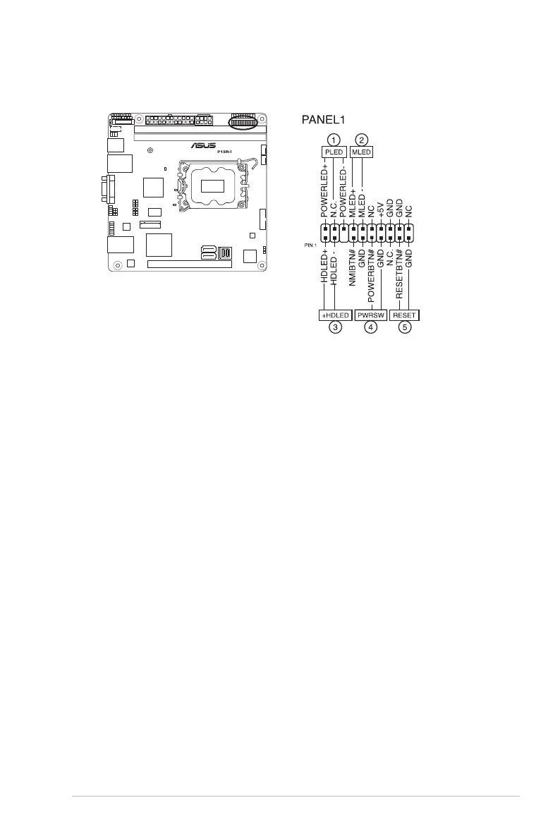
6. System panel connector (20-1 pin PANEL1)
This connector supports several chassis-mounted functions.
• System power LED (3-pin PLED)
This 3-pin connector is for the system power LED. Connect the chassis power
LED cable to this connector. The system power LED lights up when you turn on
the system power, and blinks when the system is in sleep mode.
• Message LED (2-pin MLED)
This 2-pin connector is for the message LED cable that connects to the front
message LED. The message LED is controlled by Hardware monitor to indicate
an abnormal event occurrence.
• Hard disk drive activity LED (2-pin +HDLED)
This 2-pin connector is for the HDD Activity LED. Connect the HDD Activity LED
cable to this connector. The LED lights up or flashes when data is read from or
written to the HDD.
• Power button/soft-off button (2-pin PWRSW)
This connector is for the system power button. Pressing the power button turns
the system on or puts the system in sleep or soft-off mode depending on the
BIOS settings. Pressing the power switch for more than four (4) seconds while the
system is ON turns the system OFF.
• Reset button (2-pin RESET)
This 2-pin connector is for the chassis-mounted reset button for system reboot
without turning off the system power.
Bekijk gratis de handleiding van Asus P13R-I, stel vragen en lees de antwoorden op veelvoorkomende problemen, of gebruik onze assistent om sneller informatie in de handleiding te vinden of uitleg te krijgen over specifieke functies.
Productinformatie
| Merk | Asus |
| Model | P13R-I |
| Categorie | Niet gecategoriseerd |
| Taal | Nederlands |
| Grootte | 6669 MB |


