Asus EBS-A700 handleiding
Handleiding
Je bekijkt pagina 26 van 57
ASUS EBS-A700
2-8
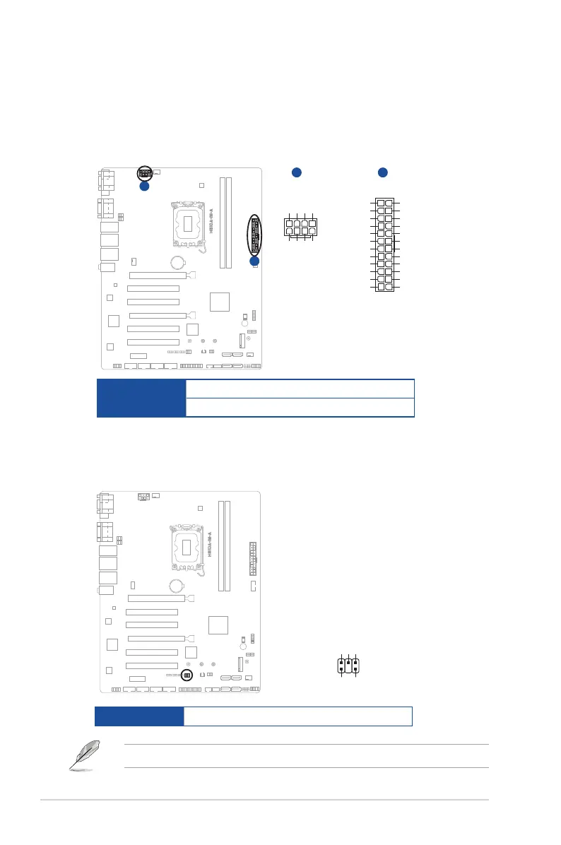
1. ATX Power connectors (24-pin ATXPWR, 2 x 4-pin EATX12V)
Correctly orient the ATX power supply plugs into these connectors and push
down rmly until the connectors completely t.
PIN 1
GND
+5 Volts
+5 Volts
+5 Volts
floating
GND
GND
GND
PSON#
GND
-12 Volts
+3 Volts
+3 Volts
+12 Volts
+12 Volts
+5V Standby
Power OK
GND
+5 Volts
GND
+5 Volts
GND
+3 Volts
+3 Volts
A
B
EATX12V
BA
ATX_PWR
PIN 1
GND
GND
GND
GND
+12V
+12V
+12V
+12V
Connector type
POWER CON 24P S/T
POWER CON 8P S/T
2. COM Debug header (COM_DEBUG)
This header allows connection to a COM Debug card.
COM_DEBUG
PIN 1
GND
GND
debug_control
TXD
+3V
The COM Debug Card is purchased separately.
Connector type HEADER 2x3p, K3, 2.54 mm pitch, S/T
2.5 Internal connectors
Bekijk gratis de handleiding van Asus EBS-A700, stel vragen en lees de antwoorden op veelvoorkomende problemen, of gebruik onze assistent om sneller informatie in de handleiding te vinden of uitleg te krijgen over specifieke functies.
Productinformatie
| Merk | Asus |
| Model | EBS-A700 |
| Categorie | Niet gecategoriseerd |
| Taal | Nederlands |
| Grootte | 4388 MB |


