Asrock NUC BOX-155H handleiding
Handleiding
Je bekijkt pagina 28 van 56
NUCS Ultra 100 BOX Series
20 21
English
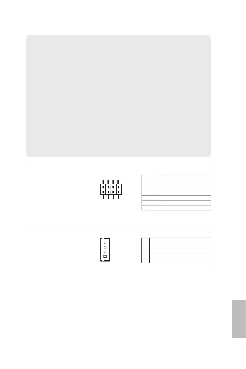
JP1 Header
(8-pin JP1)
(
see p. 18, No. 6)
* Auto clear CMOS when system boot improperly.
PWRBTN (Power Switch):
Connect to the power switch on the chassis front panel. You may congure the way to turn
o your system using the power switch.
RESET (Reset Switch):
Connect to the reset switch on the chassis front panel. Press the reset switch to restart the
computer if the computer freezes and fails to perform a normal restart.
PLED (System Power LED):
Connect to the power status indicator on the chassis front panel. e LED is on when the
system is operating. e LED keeps blinking when the system is in S3 sleep state. e LED
is o when the system is in S4 sleep state or powered o (S5).
HDLED (Hard Drive Activity LED):
Connect to the hard drive activity LED on the chassis front panel. e LED is on when the
hard drive is reading or writing data.
The front panel design may differ by chassis. A front panel module mainly consists of
power switch, reset switch, power LED, hard drive activity LED, speaker and etc. When
connecting your chassis front panel module to this header, make sure the wire assignments
and the pin assignments are matched correctly.
4-pin DC-In Wafer (BOM option)
(4-pin DC-IN1)
(see p. 18, No. 7)
4
1
Pin Signal Name
1
GND
2
DC Input
3
DC Input
4
GND
1
2
7
8
Pin Signal Name
JP1_13 Reserved JP for AT (Default)
JP1_68
Reserved JP for Clear CMOS
(Default)
JP1_12 SIO AT Mode
JP1_46 Clear CMOS
JP1_57 DACC* (Default)
Bekijk gratis de handleiding van Asrock NUC BOX-155H, stel vragen en lees de antwoorden op veelvoorkomende problemen, of gebruik onze assistent om sneller informatie in de handleiding te vinden of uitleg te krijgen over specifieke functies.
Productinformatie
| Merk | Asrock |
| Model | NUC BOX-155H |
| Categorie | Niet gecategoriseerd |
| Taal | Nederlands |
| Grootte | 4567 MB |


