Arecont Vision MicroDome Duo AV10655DN-08 handleiding
Handleiding
Je bekijkt pagina 17 van 32
Microdome Duo® Installation Manual
Page | 17 support@arecontvision.com
+1.818.937.0700 | 877.CAMERA.8 | www.arecontvision.com | avsales@arecontvision.com
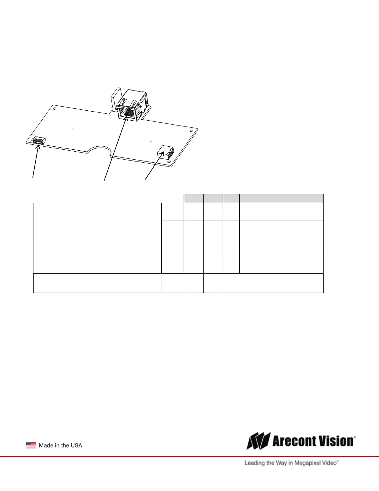
Connecting Digital I/O
1. To use digital I/O use 5-wire pigtail cable (included) and plug it into I/O connector (Pic 13). The color
coding is shown in Table 1 below
PIC. 20
5-Pin I/O Connector PoE Connector AC/DC Connector
Electrical Characteristics
MIN
MAX
PIN
I/O CABLE WIRE COLOR
Input Voltage (V)
(Measured between “+” and “–“ terminals)
ON
2.9
6.3
3
WHITE (OUT +)
OFF
0
1.3
4
BLACK (OUT -)
Output Current (mA)
(Measured between “+” and “–“ terminals)
Applied Voltage Range: 0-80V
ON
-
50
1
ORANGE (OUT +)
OFF
-
0.1
2
YELLOW (OUT -)
GROUND
5
GREEN
Table 1.
The output consists of an optically coupled solid state relay (SSR) and the input has an optocoupler. Both the
SSR and optocoupler have an isolation voltage of 1500 VRMS between the external terminals and internal
camera circuitry. The input is further protected with a serial 250Ω resistor and a debouncing circuit.
Bekijk gratis de handleiding van Arecont Vision MicroDome Duo AV10655DN-08, stel vragen en lees de antwoorden op veelvoorkomende problemen, of gebruik onze assistent om sneller informatie in de handleiding te vinden of uitleg te krijgen over specifieke functies.
Productinformatie
| Merk | Arecont Vision |
| Model | MicroDome Duo AV10655DN-08 |
| Categorie | Bewakingscamera |
| Taal | Nederlands |
| Grootte | 7655 MB |