American Audio P64 LED Plus handleiding
Handleiding
Je bekijkt pagina 4 van 8
Operating Modes:
You can use the P64 LED Plus in four ways:
• Sound-Active mode - The unit will react to sound, chasing through
the built in programs.
• Auto Mode - The unit will automatically chase through the different
colors.
• RGB Mode - Choose a single color or colors to stay static.
• DMX control mode - This function will allow you to control each
individual fixtures traits with a standard DMX 512 controller such as
as the Elation® Show Designer™.
Sound Active Mode:
In this mode the P64 LED Plus will react to sound, and chase through
the different colors.
1. Plug the fixture in and put dipswitch #10 in the “ON” postion.
2. The fixture will now change via sound.
Auto Mode:
1. Plug the fixture in and put dipswitches # 9 and 10 in the “ON”
postion.
2. Adjust the speed by adjusting dipswitches 1-7.
RGB Mode:
1. Plug the fixture in and put dipswitches #8, 9, and 10 in the “ON”
postion.
2. Dipswitch #1 alone will project Red at 25% intensity, dipswitch #2
alone will project Red at 50% intensity. Combine dipswitches 1 & 2
and Red will be projected at 100% intensity.
Dipswitch #3 alone will project Green at 25% intensity, dipswitch
#4 alone will project Green at 50% intensity. Combine dipswitches
3 & 4 and Green will be projected at 100% intensity.
Dipswitch #5 alone will project Blue at 25% intensity, dipswitch #6
alone will project Blue at 50% intensity. Combine dipswitches 5 & 6
and Blue will be projected at 100% intensity.
DMX Mode:
Operating through a DMX controller give the user the freedom to cre-
ate their own programs tailored to their own individual needs. This
P64 LED Plus Operating Instructions
©American DJ Supply® - www.americandj.com - P64 LED Plus Instruction Manual Page 8
©American DJ Supply® - www.americandj.com - P64 LED Plus Instruction Manual Page 7
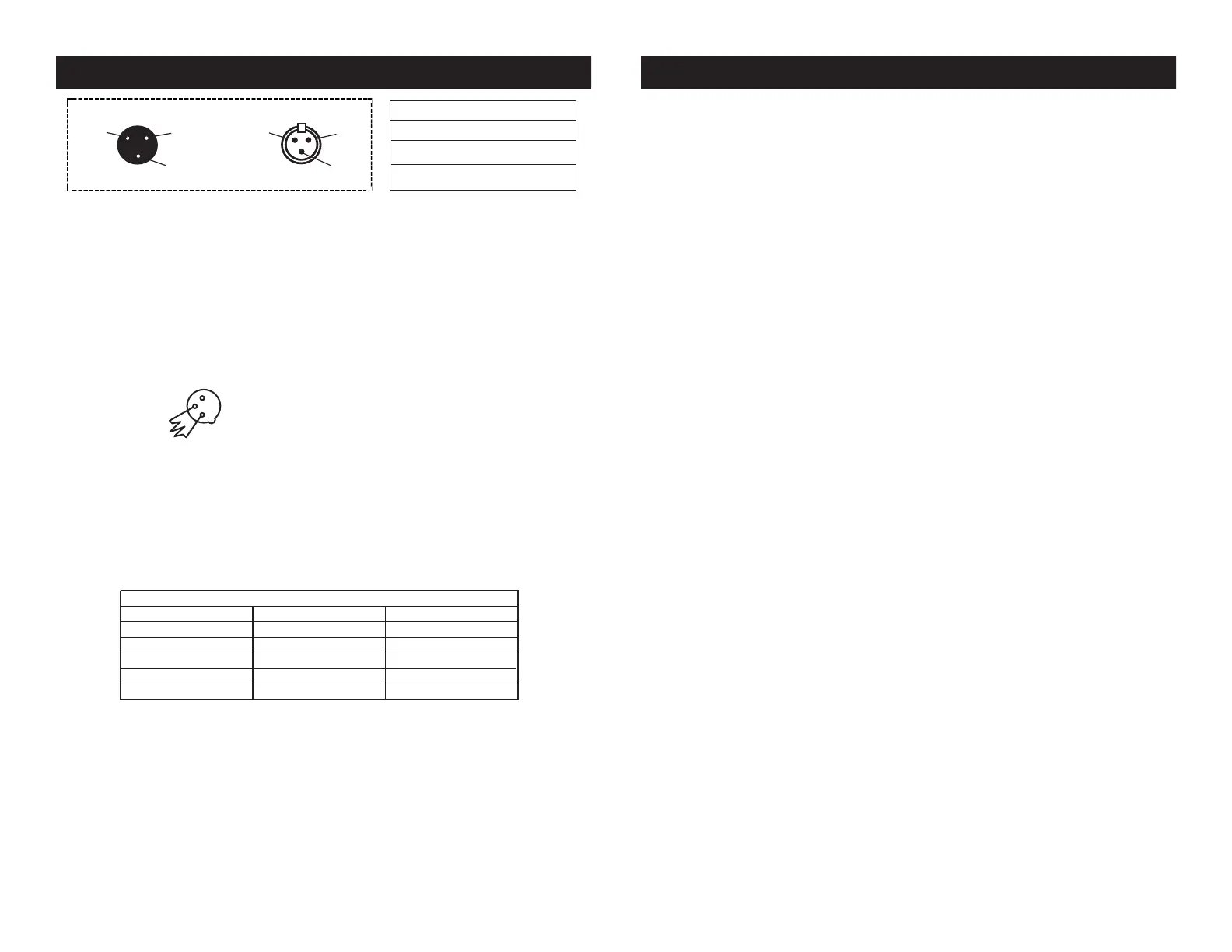
P64 LED Plus Set Up
Figure 3
1 Ground
1 Ground
XLR Male Socket
XLR Pin Conguration
3 Hot
2 Cold
2 Cold
3 Hot
XLR Female Socket
Pin 3 = Data True (positive)
Pin 2 = Data Compliment (negative)
Pin 1 = Ground
Special Note: Line Termination.
When longer runs of cable are
used, you may need to use a terminator on the last unit to avoid erratic
behavior. A terminator is a 110-120 ohm 1/4 watt resistor which is con-
nected between pins 2 and 3 of a male XLR connector (DATA + and
DATA -). This unit is inserted in the female XLR connector of the last
unit in your daisy chain to terminate the line. Using a cable terminator
(ADJ part number Z-DMX/T) will decrease the possibilities of erratic
behavior.
DMX512 IN
3-PIN XLR
SOUND
REMOTE
CONTROL
INPUT
POWER
INPUT OUTPUT
SOUND
REMOTE
CONTROL
INPUT
POWER
INPUT OUTPUT
SOUND
REMOTE
CONTROL
INPUT
POWER
INPUT OUTPUT
DMX512
DMX+,DMX-,COMMON
1
2
3
Termination reduces signal errors and
avoids signal transmission problems
and interference. It is always advisable
to connect a DMX terminal, (Resistance
120 Ohm 1/4 W) between PIN 2 (DMX-)
and PIN 3 (DMX +) of the last fixture.
1
2
3
1
2
3
DMX +
DMX -
COMMON
DMX512 OUT
3-PIN XLR
Figure 4
5-Pin XLR DMX Connectors.
Some manufactures use 5-pin DMX-
512 data cables for DATA transmission in place of 3-pin. 5-pin DMX
xtures may be implemented in a 3-pin DMX line. When inserting stan-
dard 5-pin data cables in to a 3-pin line a cable adaptor must be used,
these adaptors are readily available at most electric stores. The chart
below details a proper cable conversion.
Conductor 5-Pin XLR Male (In)3-Pin XLR Female (Out)
Pin 1
Do Not Use
Do Not Use
Pin 3
Pin 2
Pin 1
Pin 3
Pin 2
Not Used
Not Used
Data True (+ signal)
Data Compliment (- signal)
Ground/Shield
3-Pin XLR to 5-Pin XLR Conversion
Bekijk gratis de handleiding van American Audio P64 LED Plus, stel vragen en lees de antwoorden op veelvoorkomende problemen, of gebruik onze assistent om sneller informatie in de handleiding te vinden of uitleg te krijgen over specifieke functies.
Productinformatie
| Merk | American Audio |
| Model | P64 LED Plus |
| Categorie | Niet gecategoriseerd |
| Taal | Nederlands |
| Grootte | 1710 MB |


