Advantech SQF-P10 P8 handleiding
Handleiding
Je bekijkt pagina 12 van 49
SQFlash
CompactFlash Card
Specifications subject to change without notice, contact your sales representatives for the most update information.
REV 1.7 Page 12 of 49 Feb. 3, 2014
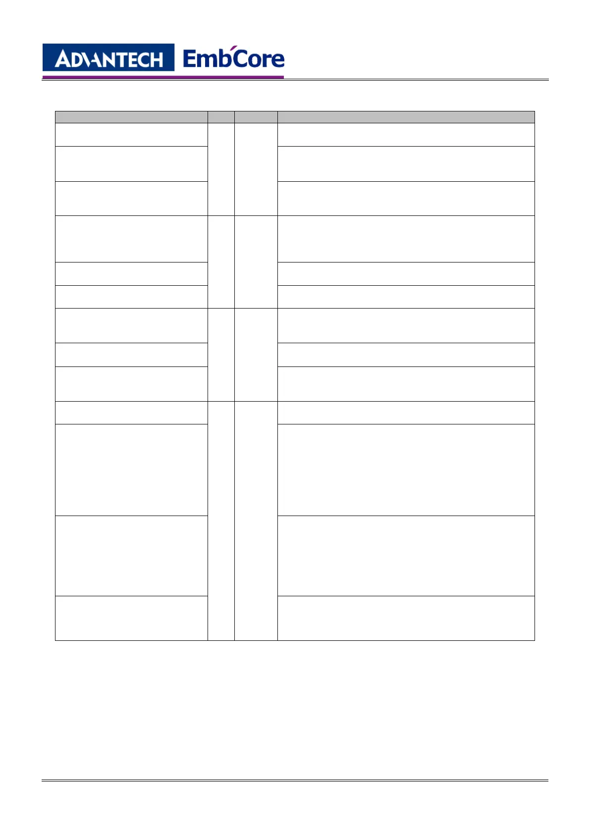
6.2 Signal Descriptions
Signal Name
Dir.
Pin
Description
BVD2
(PC Card Memory Mode)
I/O
45
This output line is always driven to a high state in Memory
Mode since a battery is not required for this product
-SPKR
(PC CARD I/O Mode)
This output line is always driven to a high state in I/O
Mode since this product does not support the audio
function
-DASP
(True IDE Mode)
In the True IDE Mode, this input/output is the Disk
Active/Slave Present signal in the Master/Slave
handshake protocol
-CD1,-CD2
(PC Card Memory Mode)
O
26, 25
These card detect pins are connected to the ground on
the CompactFlash
TM
Storage Card. They are used by
the host to determine that the CompactFlash
TM
Storage
Card is fully inserted into its socket.
-CD1,-CD2
(PC Card I/O Mode)
The signal is the same for all modes
-CD1,-CD2
(True IDE Mode)
The signal is the same for all modes
D[15:0]
(PC Card Memory Mode)
I/O
31, 30,
29, 28,
27, 49,
48, 47,
6, 5, 4,
3, 2, 23,
22, 21
These lines carry the Data, Commands, and Status
information between the host and the controller. D00 is
the LSB of the Odd Byte of the World
D[15:0]
(PC Card I/O Mode)
The signal is the same as the PC Card Memory Mode
signal.
D[15:0]
(True IDE Mode)
In True IDE Mode, all Task File operations occur in byte
mode on the lower order bus D00-D07 while all data
transfers are 16 bit using D00-D15.
-IOWR
(PC Card Memory Mode)
I
35
This signal is not used in this mode.
-IOWR
(PC Card I/O Mode)
The I/O Write strobe pulse is used to clock I/O data on the
Card Data bus into the CompactFlash
TM
Storage Card or
CF+ Card controller registers when the CompactFlash
TM
Storage Card or CF+ Card is configured to use the I/O
interface.
The clocking shall occur on the negative to positive edge
of the signal (trailing edge).
-IOWR
(True IDE Mode – Except Ultra
DMA Protocol Active)
In True IDE Mode, while Ultra DMA mode protocol is not
active, this signal has the same function as in PC Card
I/O Mode.
When Ultra DMA mode protocol is supported, this signal
must be negated before entering Ultra DMA mode
protocol.
STOP
(True IDE Mode – Ultra DMA
Protocol Active)
In True IDE Mode, while Ultra DMA mode protocol is
active, the assertion of this signal causes the termination
of the Ultra DMA burst.
Bekijk gratis de handleiding van Advantech SQF-P10 P8, stel vragen en lees de antwoorden op veelvoorkomende problemen, of gebruik onze assistent om sneller informatie in de handleiding te vinden of uitleg te krijgen over specifieke functies.
Productinformatie
| Merk | Advantech |
| Model | SQF-P10 P8 |
| Categorie | Niet gecategoriseerd |
| Taal | Nederlands |
| Grootte | 7715 MB |
Caratteristiche Prodotto
| Kleur van het product | Black, Blue, White |
| Breedte | 42.8 mm |
| Diepte | 36.4 mm |
| Hoogte | 3.3 mm |
| Intern geheugentype | SLC |


