Advantech PCM-3718H handleiding
Handleiding
Je bekijkt pagina 61 van 80
53 Chapter 7
7.2 Counter Read/write and Control Register
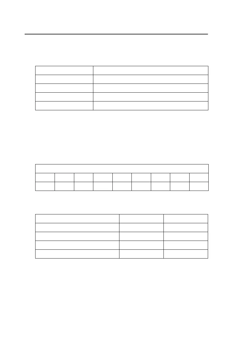
The 8254 programmable interval timer uses four registers at addresses
BASE+12, BASE+13, BASE+14 and BASE+15. Register functions are
listed below:
Since the 8254 counter uses a 16-bit structure, each section of read/write
data is split into a least significant byte (LSB) and most significant byte
(MSB). To avoid errors it is important that you make read/write opera-
tions in pairs and keep track of the byte order.
The data format for the control register appears below:
SC1 & SC0 Select counter
Register Function
BASE+12 Counter 0 read/write
BASE+13 Counter 1 read/write
BASE+14 Counter 2 read/write
BASE+15 Counter control word
BASE+15 - 8254 control, standard mode
Bit D7 D6 D5 D4 D3 D2 D1 D0
Value SC1 SC0 RW1 RW0 M2 M1 M0 BCD
Counter SC1 SC0
000
101
210
Read-back command 1 1
Bekijk gratis de handleiding van Advantech PCM-3718H, stel vragen en lees de antwoorden op veelvoorkomende problemen, of gebruik onze assistent om sneller informatie in de handleiding te vinden of uitleg te krijgen over specifieke functies.
Productinformatie
| Merk | Advantech |
| Model | PCM-3718H |
| Categorie | Niet gecategoriseerd |
| Taal | Nederlands |
| Grootte | 5483 MB |


