Advantech PCM-3718H handleiding
Handleiding
Je bekijkt pagina 52 van 80
PCM-3718 Series User Manual 44
Chapter 5 A/D Conversion
5.1 A/D Data Format and Status Register
Since the PCM-3718 cards use 12-bit A/D conversions, a single 8-bit reg-
ister will not accommodate all the data. The PCM-3718 cards therefore
store A/D data in two registers located at addresses BASE+0 and
BASE+1.
The A/D low byte data is stored in bits D4 to D7 (AD0 to AD3) of
BASE+0 and high byte data is stored in bits D0 to D7 (AD4 to AD11) of
BASE+1. The least significant bit is AD0 and the most significant bit is
AD11. You can read the source channel number corresponding to the A/
D data from bits D0 to D3 (C0 to C3) of BASE+0.
A/D data register format is:
The A/D status register at BASE+8 (read only) gives information on A/D
configuration and operation.
A/D status register format is:
Bits in this register indicate the end of conversion status, single-ended/
differential input, interrupt status and the number of the channel to be
converted next. Refer to page 33, A/D Status Register, for more
information.
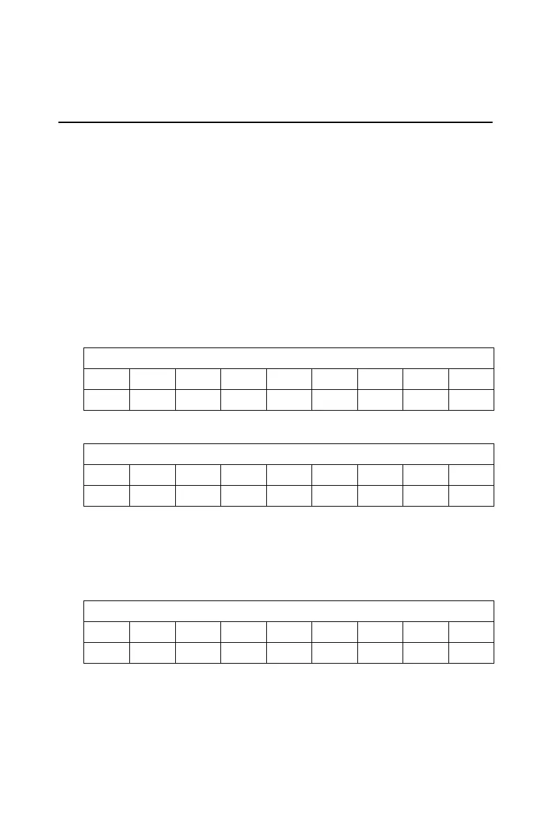
BASE+0 (read only) - A/D low byte & channel number
Bit D7 D6 D5 D4 D3 D2 D1 D0
Value AD3 AD2 AD1 AD0 C3 C2 C1 C0
BASE+1 (read only) - A/D high byte
Bit D7 D6 D5 D4 D3 D2 D1 D0
Value AD11 AD10 AD9 AD8 AD7 AD6 AD5 AD4
BASE+8 - A/D status
Bit D7 D6 D5 D4 D3 D2 D1 D0
Value EOC N/A MUX INT CN3 CN2 CN1 CN0
Bekijk gratis de handleiding van Advantech PCM-3718H, stel vragen en lees de antwoorden op veelvoorkomende problemen, of gebruik onze assistent om sneller informatie in de handleiding te vinden of uitleg te krijgen over specifieke functies.
Productinformatie
| Merk | Advantech |
| Model | PCM-3718H |
| Categorie | Niet gecategoriseerd |
| Taal | Nederlands |
| Grootte | 5483 MB |


