Advantech PCL-833 handleiding
Handleiding
Je bekijkt pagina 22 van 28
PCL-833 User Manual 14
3.1 Quadrature Encoder Introduction
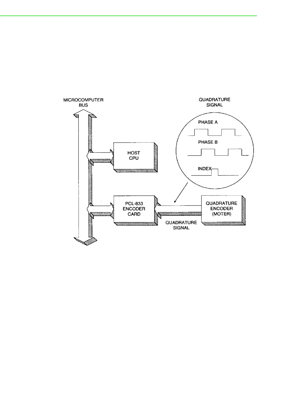
In typical closed-loop control systems, also know as servo systems, the encoder
interface senses motor position and sends a position signal to the controller. The dia-
gram below shows a typical servo system.
The encoder generates pulses which indicate the shaft position. The encoder output
includes two signals, commonly called channel A and channel B, which generate N
pulses per revolution. The two signals are shifted by a quarter of a cycle, as shown
below. The shift between the two signals enables the controller to determine the
direction of rotation, depending on whether channel A leads channel B or vice versa.
(encoder. tif)
3.1.1 Single-ended vs. differential input
Most encoders produce square wave signals with TTL levels. Industrial systems
often use encoders with differential signals, i. e. channel A and B and their comple-
ments. Differential signals can reduce sensitivity to noise and allow longer transmis-
sion distances. Encoders may also produce a third signal once per revolution known
as the index or marker. The encoder interface can use the index signal to reset the
counter, allowing you to monitor the position within the current revolution.
Bekijk gratis de handleiding van Advantech PCL-833, stel vragen en lees de antwoorden op veelvoorkomende problemen, of gebruik onze assistent om sneller informatie in de handleiding te vinden of uitleg te krijgen over specifieke functies.
Productinformatie
| Merk | Advantech |
| Model | PCL-833 |
| Categorie | Niet gecategoriseerd |
| Taal | Nederlands |
| Grootte | 1770 MB |


