Advantech PCIE-1816H handleiding
Handleiding
Je bekijkt pagina 21 van 62
15 PCIE-1816_1816H User Manual
Chapter 3 Signal Connections
3.2.1 Board ID (SW1)
The PCIE-1816/1816H has a built-in DIP switch (SW1), which is used to define each
card’s board ID. When there are multiple cards on the same chassis, this board ID
switch is useful for identifying each card’s device number.
After setting each PCIE-1816/1816H, you can identify each card in system with differ-
ent device numbers. The default value of board ID is 0 and if you need to adjust it to
other value, please set the SW1 by referring to Table 3.1.
Default Setting is 0
3.2.2 Power On Configuration(JP1)
Default configuration after power on, and hardware reset is to set all the analog input
and analog output channels to open status (the current of the load can’t be sink) so
that the external devices will not be damaged when the system starts or resets.
When the system is hot reset, then the status of isolated digital output channels are
selected by jumper JP1. Table 3.2 shows the configuration of jumper JP1.
Table 3.1: Board ID Setting (SW1)
SW1 Position 1 Position 2 Position 3 Position 4
BoardID ID0 ID1 ID2 ID3
0ONONONON
1 OFF ON ON ON
2 ON OFF ON ON
3 OFF OFF ON ON
4 ON ON OFF ON
5 OFF ON OFF ON
6 ON OFF OFF ON
7 OFF OFF OFF ON
8ONONONOFF
9 OFF ON ON OFF
10 ON OFF ON OFF
11 OFF OFF ON OFF
12 ON ON OFF OFF
13 OFF ON OFF OFF
14 ON OFF OFF OFF
15 OFF OFF OFF OFF
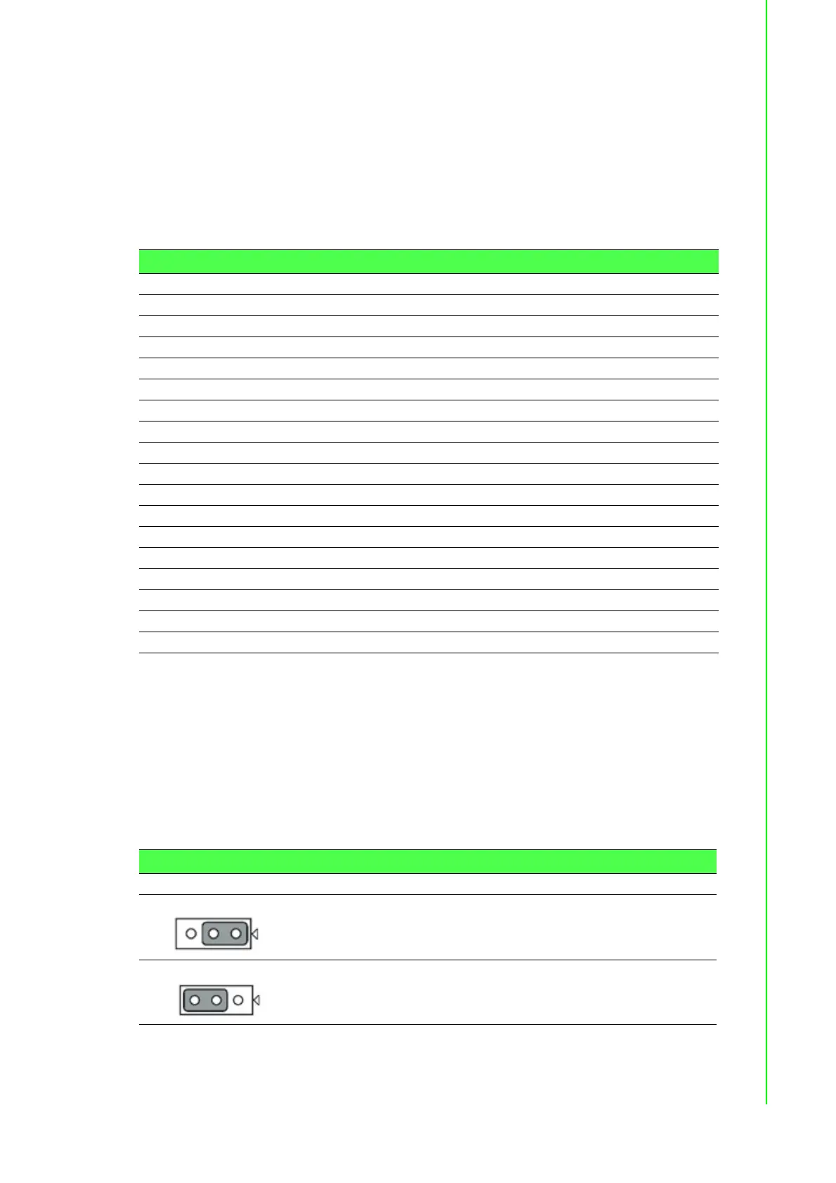
Table 3.2: Power on Configuration after Hot Reset (JP1)
JP1 Power on configuration after hot reset
1
Keep last status after hot reset
1
Default configuration (Default setting)
Bekijk gratis de handleiding van Advantech PCIE-1816H, stel vragen en lees de antwoorden op veelvoorkomende problemen, of gebruik onze assistent om sneller informatie in de handleiding te vinden of uitleg te krijgen over specifieke functies.
Productinformatie
| Merk | Advantech |
| Model | PCIE-1816H |
| Categorie | Niet gecategoriseerd |
| Taal | Nederlands |
| Grootte | 9278 MB |


