Advantech PCIE-1751 handleiding
Handleiding
Je bekijkt pagina 27 van 38
19 PCIE-1751 User Manual
Chapter 3 Signal Connections
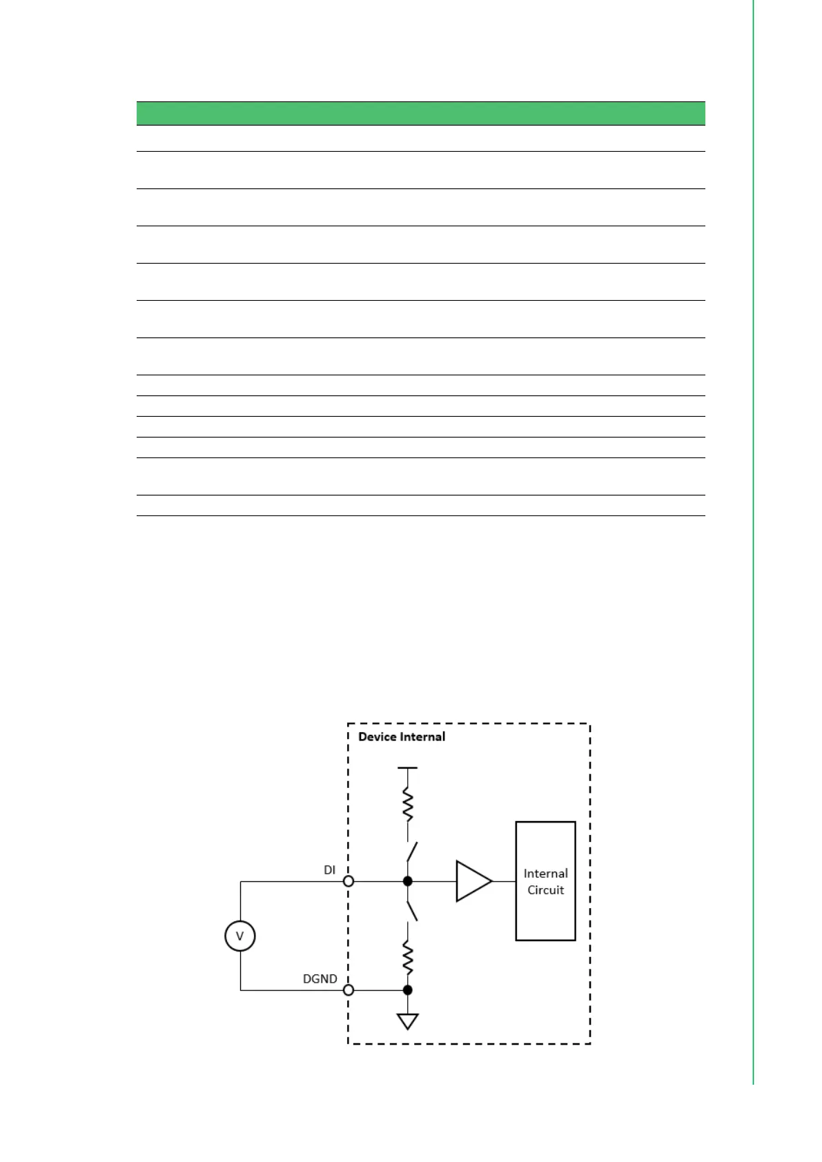
Digital Input (TTL DI/O, Pull-Up/Down)
A digital input/output (DI/O) channel can be configured by software to perform digital
input measurement, which is the power-on default configuration, or digital output
generation. When performing digital input measurement, the voltage logic level
between the digital input (DI) terminal and the digital ground (DGND) terminal is mea-
sured. To prevent undetermined or fluctuating results when input is floating, the digi-
tal input channel can be configured as internally pulled-up or pulled-down by
software. This is shown in Figure 3.2.
Figure 3.2 Digital input signal connection
Table 3.4: PCIE-1751 Pin Assignments
Pin Name Direction Description Pin Number
DI/O Port 0<0..7> I/O
Bi-directional digital input/output port 0
terminals.
1 ~ 8
DI/O Port 1<0..7> I/O
Bi-directional digital input/output port 1
terminals.
10 ~ 17
DI/O Port 2<0..7> I/O
Bi-directional digital input/output port 2
terminals.
19 ~ 26
DI/O Port 3<0..7> I/O
Bi-directional digital input/output port 3
terminals.
35 ~ 42
DI/O Port 4<0..7> I/O
Bi-directional digital input/output port 4
terminals.
44 ~ 51
DI/O Port5<0..7> I/O
Bi-directional digital input/output port 5
terminals.
53 ~ 60
INT_OUT O Interrupt Out 33
CNT<0..2>_CLK I Counter 0 clock input terminal. 62, 64, 66
CNT<0..2>_OUT O Counter 0 output terminal. 28, 30, 32
CNT<0..2>_GATE I Counter 0 gate input terminal. 63, 65, 67
GND - Ground terminals for digital signals.
9, 18, 27, 29,
31, 43, 52, 61
+5V O +5 V supply output. 34, 68
Bekijk gratis de handleiding van Advantech PCIE-1751, stel vragen en lees de antwoorden op veelvoorkomende problemen, of gebruik onze assistent om sneller informatie in de handleiding te vinden of uitleg te krijgen over specifieke functies.
Productinformatie
| Merk | Advantech |
| Model | PCIE-1751 |
| Categorie | Niet gecategoriseerd |
| Taal | Nederlands |
| Grootte | 2908 MB |


