Advantech PCE-5B13-03 handleiding
Handleiding
Je bekijkt pagina 2 van 7
2 PCE-5B13(7B14)-03 Startup Manual
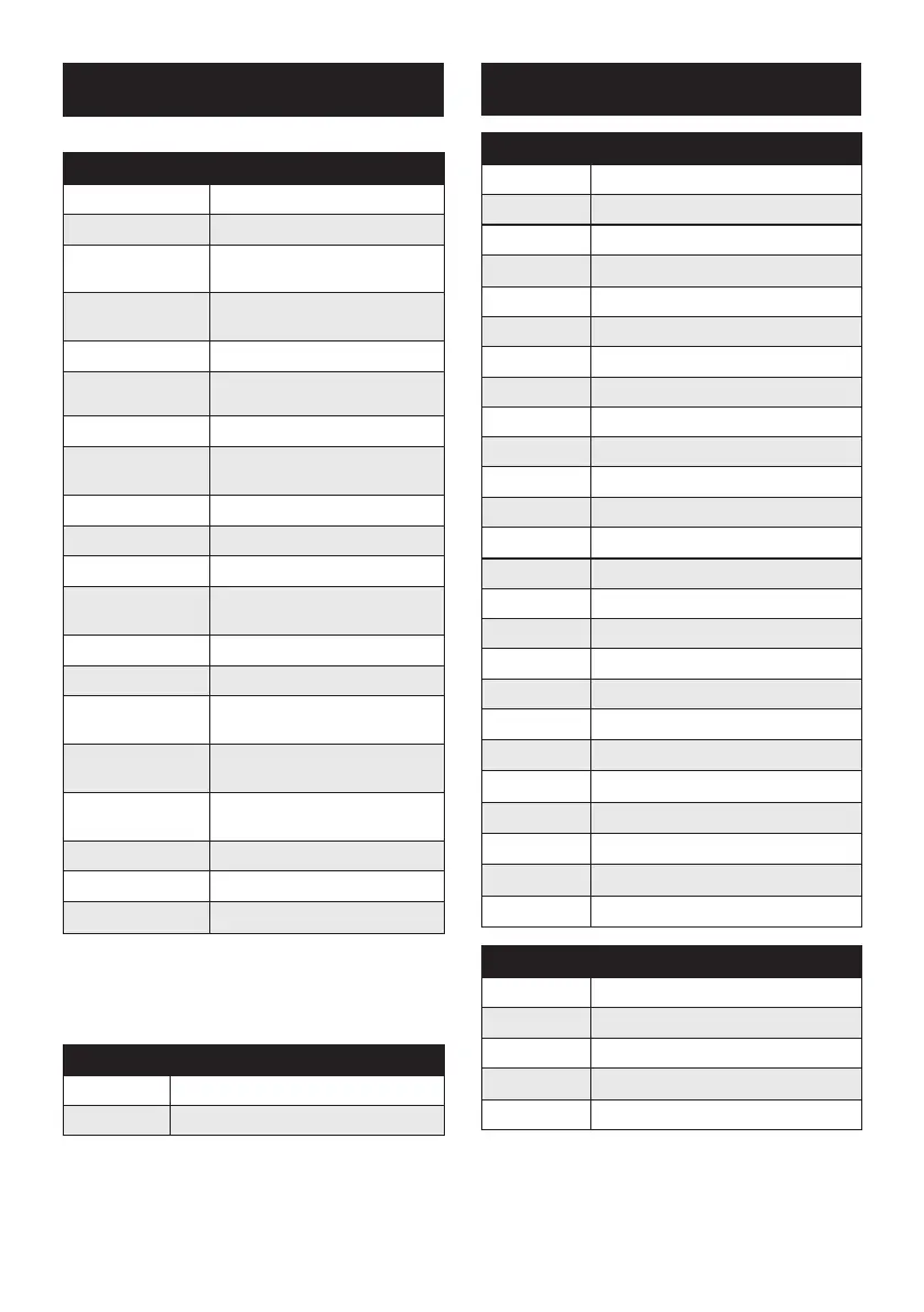
Connectors and Jumpers
This table shows the function of each jumper and connector:
Connectors
Label Function
SHBA1~SHBD1
PICMG1.3 CPU board slot
PPCIE2
PCIe x 16 slot (Only on PCE-
5B12-07)
PPCIE1, PPCIE2
PCIe p2-x8 slots (Only on PCE-
7B13-07)
P1PCIE1~P1PCIE3
PCIe p2-x4 slots
PPCI1~ PPCI3 32 Bit / 33 MHz PCI Bus slots
EATXPWR1
ATX2.0 24-pin Power Connector
EATX12V1
ATX 12V Auxiliary 8-pin Power
Connector
ATX12V1
ATX 12V 4-pin Power Connector
PWR3V1 3.3V Auxiliary Power Connector
PWR3V2
3.3V Auxiliary Power Connector
VOLT1
Alarm board / CMM Power Con-
nector
FAN1~5
FAN Connector (Horizontal Type)
FAN6~7 FAN Connector (Vertical Type)
FANDEC1
FAN speed detector Connector
(Optional)
SMBUS1~SMBUS2
System Management Bus
(Optional)
JFP1
Power and Reset button Con-
nector
IPMB1 IPMB Connector (Optional)
USB12
Two USB port pin header
USB34 Two USB port pin header
Note: In this backplane’s default conguration, FAN-
DEC1, SMBUS1~SMBUS3, IPMB1 pin-headers
are NOT populated, those footprints are reserved
for customization.
Jumpers
Label Function
PSON1
ATX / AT Mode Selection
EATXPWER1
Pin Name
1
3.3 V
2 3.3 V
3
GND
4 5 V
5
GND
6
5 V
7
GND
8 Power OK
9
5 V SBY
10
12 V
11
12 V
12 3.3 V
13
3.3 V
14 -12 V
15
GND
16 PSON#
17
GND
18 GND
19
GND
20 -5 V
21
-5 V
22 5 V
23
5 V
24 GND
ATX12V1
Pin Name
1
GND
2 GND
3
12 V
4 12 V
Connectors and Jumpers (Cont.)
Bekijk gratis de handleiding van Advantech PCE-5B13-03, stel vragen en lees de antwoorden op veelvoorkomende problemen, of gebruik onze assistent om sneller informatie in de handleiding te vinden of uitleg te krijgen over specifieke functies.
Productinformatie
| Merk | Advantech |
| Model | PCE-5B13-03 |
| Categorie | Niet gecategoriseerd |
| Taal | Nederlands |
| Grootte | 1736 MB |


