Advantech IPC-611 handleiding
Handleiding
Je bekijkt pagina 42 van 56
IPC-610 User Manual/ 用户手册 28
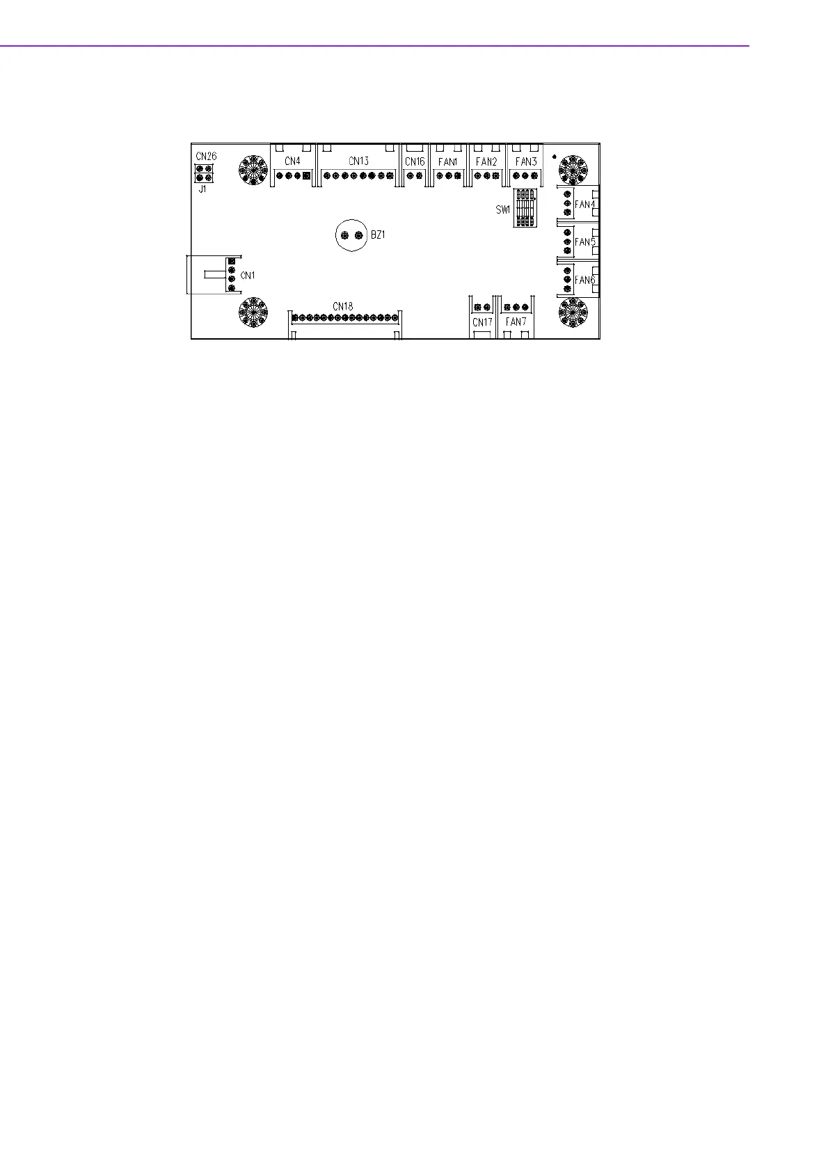
4.1 Alarm Board Layout/报警板布局/報警板零件配置
Figure 4.1 Alarm Board Layout/ 报警板布局 / 報警板零件配置
4.2 Alarm Board Specifications/ 报警板规格 / 報警板
規格
Input Power: +5V, +12V
Input Signals:
! 7 fan connectors
! One ‘thermal sensor’ connector (supports up to 8 thermal sensors in series)
! One ‘power good’ input
! One ‘alarm reset’ input
! One ‘voltage signal’ connector (connect from the backplane / motherboard, sup-
porting six voltages:
±12V, ±5V, +3.3V, and +5Vsb)
! One ‘hard disk LED’ connector (connect from the CPU card / motherboard)
Output Signals:
! One ‘LED board’ connector
! One ‘buzzer’ output
输入电源:+5 V, +12 V
输入信号:
! 7 个风扇接口
! 1 个 “热传感器”接口 (最多支持 8 个串行热传感器)
! 1 个 “电源良好”输入接口
! 1 个 “报警复位”输入接口
! 1 个“电压信号”接口(从背板 / 母板连接,支 持 6 种电压:
!
12 V,
!
5 V, +3.3
V 和 +5 Vsb)
! 1 个 “HDD LED”接口 (从 CPU 卡 / 母板连接)
输出信号:
! 1 个 “LED 板”接口
! 1 个 “蜂鸣器”输出
Bekijk gratis de handleiding van Advantech IPC-611, stel vragen en lees de antwoorden op veelvoorkomende problemen, of gebruik onze assistent om sneller informatie in de handleiding te vinden of uitleg te krijgen over specifieke functies.
Productinformatie
| Merk | Advantech |
| Model | IPC-611 |
| Categorie | Niet gecategoriseerd |
| Taal | Nederlands |
| Grootte | 8318 MB |


