Advantech iDAQ-815 handleiding
Handleiding
Je bekijkt pagina 17 van 34
7 iDAQ-815 User Manual
Chapter 2 Installation Guide
2.3 Signal Connection and Pin Assignment
2.3.1 2-Wire RTD Input Signal Connection
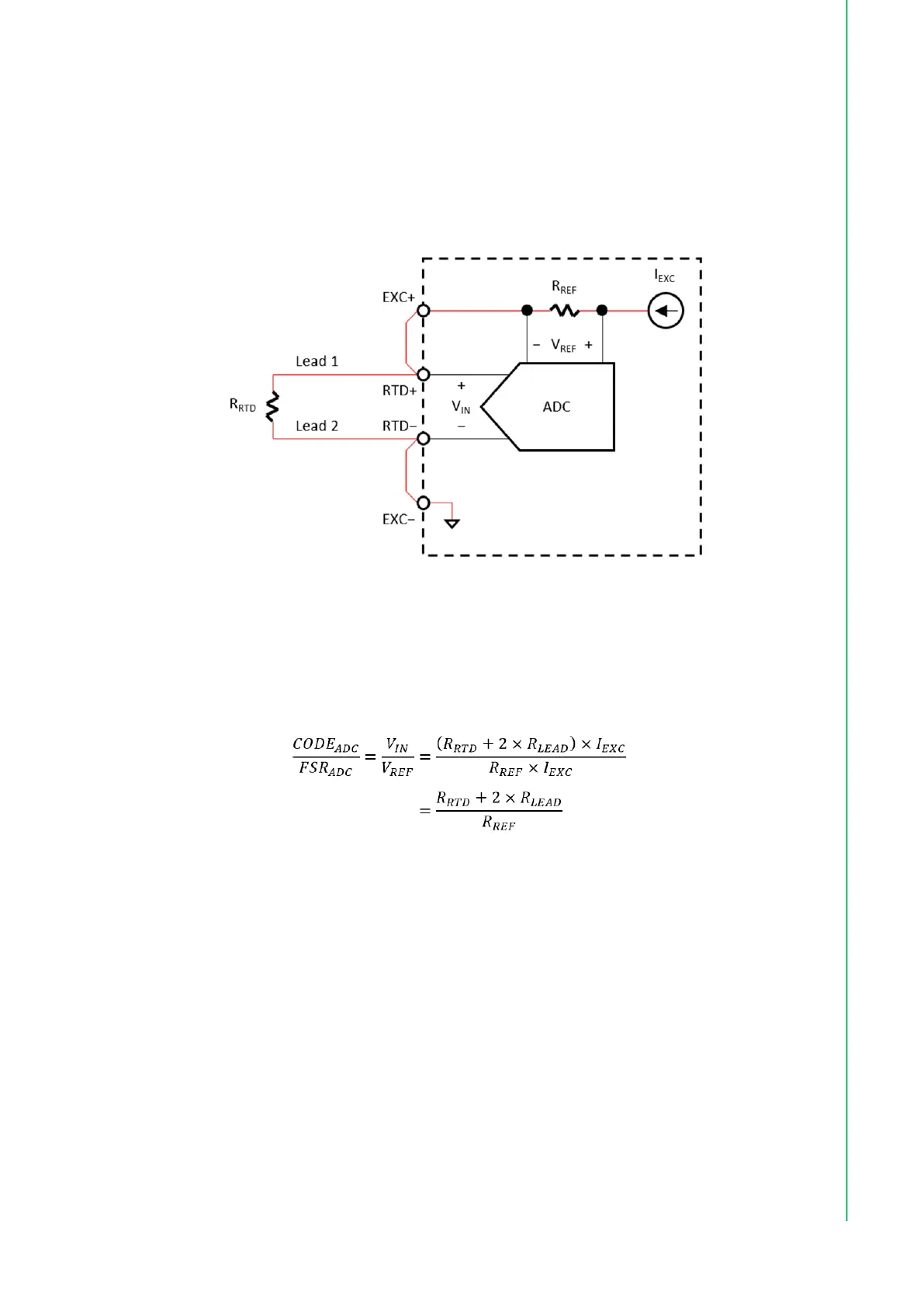
Figure 2.2 shows 2-wire RTD input signal connection. The two leads of the RTD are
connected to RTD+ and RTD- terminals. In addition, use short wires to connect
EXC+ to RTD+ and RTD− to EXC− in order to form an excitation current loop.
Figure 2.2 2-wire RTD input signal connection.
The excitation current source (I
EXC
) flows through internal reference resistor (R
REF
),
RTD lead 1, RTD resistor (R
RTD
), RTD lead 2, and to the internal ground as shown
by the red line in Figure 2.2. Assuming both lead-wire resistances are equal (R
LEAD
),
the measurement result can be calculated as follows.
where
CODE
ADC
is the output code of the ADC,
FSR
ADC
is the full-scale range of ADC (for a 24-bit ADC, it is equal to 2
24
),
V
IN
is the voltage measured by the ADC, and
V
REF
is the reference voltage of the ADC.
As can be seen in the equation, the lead-wire resistances cannot be separated from
the RTD and result in measurement errors. To minimize the errors, use lead-wire with
length as short as possible.
2.3.2 3-Wire RTD Input Signal Connection
Figure 2.3 shows 3-wire RTD input signal connection. Connect single-lead end of the
RTD to RTD+ terminal and the other two leads to RTD− and EXC− terminals. In addi-
Bekijk gratis de handleiding van Advantech iDAQ-815, stel vragen en lees de antwoorden op veelvoorkomende problemen, of gebruik onze assistent om sneller informatie in de handleiding te vinden of uitleg te krijgen over specifieke functies.
Productinformatie
| Merk | Advantech |
| Model | iDAQ-815 |
| Categorie | Niet gecategoriseerd |
| Taal | Nederlands |
| Grootte | 2727 MB |


